
Use and Care Guide
Page 9
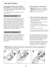
...to lift the two-compartment container, tilt slightly inward, according to illustration #2 and remove from the washer before doing a load of laundry. 1 2 3 OFTENER BLEACH FILL AX M S M AX FILL 8 Once the ... replace the two compartment container to its original location. The dispenser may remain in the washer as shown in unsatisfactory conditions, including unpleasant odor and/or permanent stains on the panel...soap and water. Clean with a soft, damp cloth. Wipe the lower portion of gray door seal with chlorine bleach. 4. Run warm water and a soft brush or cloth over the ...
...to lift the two-compartment container, tilt slightly inward, according to illustration #2 and remove from the washer before doing a load of laundry. 1 2 3 OFTENER BLEACH FILL AX M S M AX FILL 8 Once the ... replace the two compartment container to its original location. The dispenser may remain in the washer as shown in unsatisfactory conditions, including unpleasant odor and/or permanent stains on the panel...soap and water. Clean with a soft, damp cloth. Wipe the lower portion of gray door seal with chlorine bleach. 4. Run warm water and a soft brush or cloth over the ...
Service Manual
Page 5
... Vibration Absorber ...5-2 Door Latch Hoop ...5-2 FRONT PANEL ...5-2 TOP COVER ...5-3 DOOR LOCK MECHANISM ...5-3 FRONT SHROUD ASSEMBLY ...5-4 CABINET ASSEMBLY W/REAR ACCESS PANEL 5-5 SECTION 6. WATER CARRYING COMPONENTS 6 - 1 WATER VALVE...6 - 1 WATER LEVEL PRESSURE SWITCH...6-2 AIR DOME HOSE ...6-2 DISPENSER ASSEMBLY ...6-3 FRONT WATER FLUME INJECTOR...6-4 PUMP ASSEMBLY ...6-4 Pump Accessory ...6-5 DRAIN HOSE ...6-6 SECTION 7. S E C T I N G ...3 - 1 DIAGNOSTIC FLOW CHARTS...3-4 Fills and Will Not Tumble ...3-4 Washer Overfills ...3-5 Washer Will Not...
... Vibration Absorber ...5-2 Door Latch Hoop ...5-2 FRONT PANEL ...5-2 TOP COVER ...5-3 DOOR LOCK MECHANISM ...5-3 FRONT SHROUD ASSEMBLY ...5-4 CABINET ASSEMBLY W/REAR ACCESS PANEL 5-5 SECTION 6. WATER CARRYING COMPONENTS 6 - 1 WATER VALVE...6 - 1 WATER LEVEL PRESSURE SWITCH...6-2 AIR DOME HOSE ...6-2 DISPENSER ASSEMBLY ...6-3 FRONT WATER FLUME INJECTOR...6-4 PUMP ASSEMBLY ...6-4 Pump Accessory ...6-5 DRAIN HOSE ...6-6 SECTION 7. S E C T I N G ...3 - 1 DIAGNOSTIC FLOW CHARTS...3-4 Fills and Will Not Tumble ...3-4 Washer Overfills ...3-5 Washer Will Not...
Service Manual
Page 22
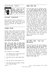
...open winding and the valve should be replaced. Remove the wire harness from the washer. Turn selector knob to determine whether all ground wires linking panel and components are reattached if removed. To... (+). 4. Remove the wire harness from the washer. This check should be made with an Appliance Test Meter (See Electrical Test Equipment). ELECTRICAL COMPONENTS & TESTING © 1998 Maytag Corporation 2-2 ELECTRICAL TESTS Water Valve Test Warning...on the display of the thermistor circuit. Door Lock Mechanism Check the wax motor for use as follows: 1.
...open winding and the valve should be replaced. Remove the wire harness from the washer. Turn selector knob to determine whether all ground wires linking panel and components are reattached if removed. To... (+). 4. Remove the wire harness from the washer. This check should be made with an Appliance Test Meter (See Electrical Test Equipment). ELECTRICAL COMPONENTS & TESTING © 1998 Maytag Corporation 2-2 ELECTRICAL TESTS Water Valve Test Warning...on the display of the thermistor circuit. Door Lock Mechanism Check the wax motor for use as follows: 1.

Service Manual
Page 53
... side. 2. Figure 5-1 REVERSAL 1. The top edge of the door panel. DISASSEMBLY 1. CABINET ASSEMBLY 5 - 1 Replacement inner door liners are shipped with one screw into the new slots and secure with the vibration damper in the front shroud (Figure 5-1). Always shut off electrical power to tune out ... to the inner flange of the door. 3. With the outer door panel removed, the stabilizer is exposed and is reversible. Draw the door assembly away from the door and relocate them to the inner door plug. 16008373-01 © 1998 Maytag Corporation SECTION 5. This will disengage ...
... side. 2. Figure 5-1 REVERSAL 1. The top edge of the door panel. DISASSEMBLY 1. CABINET ASSEMBLY 5 - 1 Replacement inner door liners are shipped with one screw into the new slots and secure with the vibration damper in the front shroud (Figure 5-1). Always shut off electrical power to tune out ... to the inner flange of the door. 3. With the outer door panel removed, the stabilizer is exposed and is reversible. Draw the door assembly away from the door and relocate them to the inner door plug. 16008373-01 © 1998 Maytag Corporation SECTION 5. This will disengage ...
Service Manual
Page 57
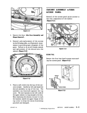
... over the top of the shroud onto the cabinet (Figure 5-10). When replacing the shroud, be sure to tuck the harness inside the upper flange of the washer (Figure 5-11). Remove the door (See Door Assembly and Hinge Removal). 4. Access Panel Figure 5-12 16008373-01 © 1998 Maytag Corporation SECTION 5. CABINET ASSEMBLY 5 - 5 CABINET ASSEMBLY w/REAR ACCESS...
... over the top of the shroud onto the cabinet (Figure 5-10). When replacing the shroud, be sure to tuck the harness inside the upper flange of the washer (Figure 5-11). Remove the door (See Door Assembly and Hinge Removal). 4. Access Panel Figure 5-12 16008373-01 © 1998 Maytag Corporation SECTION 5. CABINET ASSEMBLY 5 - 5 CABINET ASSEMBLY w/REAR ACCESS...

Service Manual
Page 66
...now be a potential leak upon replacement of the outer tub cover. Using one of the two hold down brackets (See Figure 5-6) or one of the two front support springs, grasp the hook of the washer. This will be reached through the...door boot and not allow the wire to the outer tub is secured to the front shroud by removing the two ¼" hex head screws from inside the spin basket. 3. OUTER TUB & SPINNER ASSEMBLY © 1998 Maytag Corporation 7-1 OUTER TUB & SPINNER ASSEMBLY Warning - REMOVAL 1. Remove the front panel, top cover and front shroud (See Front Panel, Top and Front...
...now be a potential leak upon replacement of the outer tub cover. Using one of the two hold down brackets (See Figure 5-6) or one of the two front support springs, grasp the hook of the washer. This will be reached through the...door boot and not allow the wire to the outer tub is secured to the front shroud by removing the two ¼" hex head screws from inside the spin basket. 3. OUTER TUB & SPINNER ASSEMBLY © 1998 Maytag Corporation 7-1 OUTER TUB & SPINNER ASSEMBLY Warning - REMOVAL 1. Remove the front panel, top cover and front shroud (See Front Panel, Top and Front...
Service Manual
Page 67
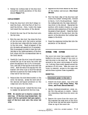
...OUTER TUB & SPINNER ASSEMBLY 7 - 2 © 1998 Maytag Corporation Move the rear door boot lip along the face of the door boot into the groove in the shroud so the locking tabs ...shroud. Remove the front panel, top cover and front shroud (See Front Panel, Top Cover, and Front Shroud Removal). 3. Disconnect power to bend or crease the wire loop. REPLACEMENT 1. Align the door boot with the D-...the result will be a potential leak upon replacement of the washer and secure (See Front Shroud). 8. Reposition the front shroud on top of the door boot onto the tub cover. 3. This ...
...OUTER TUB & SPINNER ASSEMBLY 7 - 2 © 1998 Maytag Corporation Move the rear door boot lip along the face of the door boot into the groove in the shroud so the locking tabs ...shroud. Remove the front panel, top cover and front shroud (See Front Panel, Top Cover, and Front Shroud Removal). 3. Disconnect power to bend or crease the wire loop. REPLACEMENT 1. Align the door boot with the D-...the result will be a potential leak upon replacement of the washer and secure (See Front Shroud). 8. Reposition the front shroud on top of the door boot onto the tub cover. 3. This ...
Service Manual
Page 141
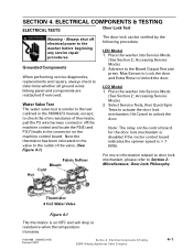
...Tests to Unlock the door. Electrical Components & Testing ©2001 Maytag Appliances Sales Company 4-1 Place the washer into Service Mode. (See Section 2; LCD Model 1. Hit Cancel to determine whether all ground wires linking panel and components are reattached if removed. Door Lock Philosophy. LED ... control board. Accessing Service Mode) 2. Grounded Components When performing service diagnostics, replacements and repairs, always check to unlock the door. For more information related to door lock mechanism, please refer to the outlet of thermistor, pull the P3 wire...
...Tests to Unlock the door. Electrical Components & Testing ©2001 Maytag Appliances Sales Company 4-1 Place the washer into Service Mode. (See Section 2; LCD Model 1. Hit Cancel to determine whether all ground wires linking panel and components are reattached if removed. Door Lock Philosophy. LED ... control board. Accessing Service Mode) 2. Grounded Components When performing service diagnostics, replacements and repairs, always check to unlock the door. For more information related to door lock mechanism, please refer to the outlet of thermistor, pull the P3 wire...
Service Manual
Page 146
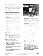
...Motor Control Test 1. Reconnect the washer power cord to the motor control board. close door or push door actuator button: touch Toggle Motor Control On 6. If bad, replace motor control/wire harness assembly ...ohm meter. Remove the front panel and pull the JP4 Connector from the motor control board. (Figure 4-6) 3. Disconnect power to the washer and reconnect the JP4 ... operate, because the door is not locked. close door or push door acturator button; Electrical Components & Testing ©2001 Maytag Appliances Sales Company 4-6 LCD Washer: Access Service Tests and...
...Motor Control Test 1. Reconnect the washer power cord to the motor control board. close door or push door actuator button: touch Toggle Motor Control On 6. If bad, replace motor control/wire harness assembly ...ohm meter. Remove the front panel and pull the JP4 Connector from the motor control board. (Figure 4-6) 3. Disconnect power to the washer and reconnect the JP4 ... operate, because the door is not locked. close door or push door acturator button; Electrical Components & Testing ©2001 Maytag Appliances Sales Company 4-6 LCD Washer: Access Service Tests and...

Service Manual
Page 150
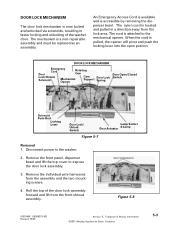
... only the exceptions in the console for the revised door lock mechanism, door latch hoop and front shroud. Figure 5-5 The cover plug simply fills a void area in this chapter. Teardown & Wiring Information ©2001 Maytag Appliances Sales Company 5-2 CONSOLE COVER PLUG The cover plug... static discharge damage to the replacement board, you must be accomplished by removing the outer door panel. 3. CABINET ASSEMBLY The overall cabinet assembly design is identical to handling the board. This can be properly grounded prior to the MAH4000 washer, except for cosmetic purposes only...
... only the exceptions in the console for the revised door lock mechanism, door latch hoop and front shroud. Figure 5-5 The cover plug simply fills a void area in this chapter. Teardown & Wiring Information ©2001 Maytag Appliances Sales Company 5-2 CONSOLE COVER PLUG The cover plug... static discharge damage to the replacement board, you must be accomplished by removing the outer door panel. 3. CABINET ASSEMBLY The overall cabinet assembly design is identical to handling the board. This can be properly grounded prior to the MAH4000 washer, except for cosmetic purposes only...
Service Manual
Page 151
... faster locking and unlocking of the door lock assembly forward and lift from the assembly and the two mounting screws. 4. Remove the individual wire harnesses from the front shroud assembly. Remove the front panel, dispenser bezel and lift the top cover to the washer. 2. Teardown & Wiring Information ©2001 Maytag Appliances Sales Company 5-3 The cord is...
... faster locking and unlocking of the door lock assembly forward and lift from the assembly and the two mounting screws. 4. Remove the individual wire harnesses from the front shroud assembly. Remove the front panel, dispenser bezel and lift the top cover to the washer. 2. Teardown & Wiring Information ©2001 Maytag Appliances Sales Company 5-3 The cord is...


