
Service Manual
Page 4
... & Motor Control Test ...2-8 Motor Phase Test ...2-8 Motor Windings Check ...2-9 Tachometer Circuit Diagnostics ...2-10 UNBALANCE CONTROL SYSTEM ...2 - 1 1 Tub Displacement Switch ...2 - 1 2 Strut Displacement Switch ...2 - 1 2 Inertial Unbalance Switch ...2 - 1 3 Cabinet Vibration Sensor ...2 - 1 3 Cabinet Vibration Absorber ...2 - 1 3 16008373-01 © 1998 Maytag Corporation CONTENTS ii GENERAL INFORMATION ...1 - 1 PRE-INSTALLATION REQUIREMENTS ...1 - 1 U N C R A T I N G ...1 - 1 I N S T A L L A T I O N...1 - 2 GROUNDING POLARITY CHECKS ...1-4 S P E C I F I C A T I O N S ...1-4 WASHER...
... & Motor Control Test ...2-8 Motor Phase Test ...2-8 Motor Windings Check ...2-9 Tachometer Circuit Diagnostics ...2-10 UNBALANCE CONTROL SYSTEM ...2 - 1 1 Tub Displacement Switch ...2 - 1 2 Strut Displacement Switch ...2 - 1 2 Inertial Unbalance Switch ...2 - 1 3 Cabinet Vibration Sensor ...2 - 1 3 Cabinet Vibration Absorber ...2 - 1 3 16008373-01 © 1998 Maytag Corporation CONTENTS ii GENERAL INFORMATION ...1 - 1 PRE-INSTALLATION REQUIREMENTS ...1 - 1 U N C R A T I N G ...1 - 1 I N S T A L L A T I O N...1 - 2 GROUNDING POLARITY CHECKS ...1-4 S P E C I F I C A T I O N S ...1-4 WASHER...

Service Manual
Page 6
... ...8 - 1 DRIVE BELT ...8 - 1 DRIVE MOTOR ...8 - 1 MACHINE CONTROL ...8-2 MOTOR CONTROL ...8-3 SECTION 9. ELECTRICAL SCHEMATICS 9 - 1 Schematic Prior to Series 17 ...9 - 1 Timer Chart Prior to Series 17 ...9-2 Schematic Series 17 ...9-3 Timer Chart Series 17 ...9-4 Schematic Series 18 ...9-5 Timer Chart Series 18 ...9-6 Schematic Series 19 ...9-7 16008373-01 © 1998 Maytag Corporation CONTENTS iv SEAL SYSTEM ...7-6 OUTER TUB ASSEMBLY ...7-7 B E A R I N G S ...7-7 COUNTER WEIGHTS ...7-7 STRUT ASSEMBLY ...7-8 Strut Displacement Switch ...7-8 INERTIAL UNBALANCE SWITCH...
... ...8 - 1 DRIVE BELT ...8 - 1 DRIVE MOTOR ...8 - 1 MACHINE CONTROL ...8-2 MOTOR CONTROL ...8-3 SECTION 9. ELECTRICAL SCHEMATICS 9 - 1 Schematic Prior to Series 17 ...9 - 1 Timer Chart Prior to Series 17 ...9-2 Schematic Series 17 ...9-3 Timer Chart Series 17 ...9-4 Schematic Series 18 ...9-5 Timer Chart Series 18 ...9-6 Schematic Series 19 ...9-7 16008373-01 © 1998 Maytag Corporation CONTENTS iv SEAL SYSTEM ...7-6 OUTER TUB ASSEMBLY ...7-7 B E A R I N G S ...7-7 COUNTER WEIGHTS ...7-7 STRUT ASSEMBLY ...7-8 Strut Displacement Switch ...7-8 INERTIAL UNBALANCE SWITCH...
Service Manual
Page 11
... the cycles options using the option switches, and starts the washer. This continues until the cycle is rotated to the next increment, reads a new set of the Neptune washer control system.) Figure 1-7 16008373-01 Prior To Series 17 © 1998 Maytag Corporation SECTION 1. These receive input signals and send output signals to the motor control. - Door lock wax...
... the cycles options using the option switches, and starts the washer. This continues until the cycle is rotated to the next increment, reads a new set of the Neptune washer control system.) Figure 1-7 16008373-01 Prior To Series 17 © 1998 Maytag Corporation SECTION 1. These receive input signals and send output signals to the motor control. - Door lock wax...
Service Manual
Page 13
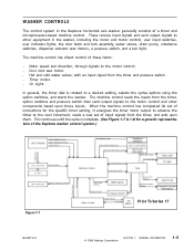
...extra rinse increments, the wash side circuit in progress, the machine control will energize the line relay and begin the sequence timing defined for each fill (See Water Valve Outputs). 16008373-01 © 1998 Maytag Corporation SECTION 1. TACH INPUT The tach input is energized. This ... a malfunction in progress, the machine control will disengage the line relay, both water valve output signals, the door lock wax motor signal, the timer motor output signal, and the on the control panel. START/STOP INPUT The start/stop the washer. When the water level drains below ...
...extra rinse increments, the wash side circuit in progress, the machine control will energize the line relay and begin the sequence timing defined for each fill (See Water Valve Outputs). 16008373-01 © 1998 Maytag Corporation SECTION 1. TACH INPUT The tach input is energized. This ... a malfunction in progress, the machine control will disengage the line relay, both water valve output signals, the door lock wax motor signal, the timer motor output signal, and the on the control panel. START/STOP INPUT The start/stop the washer. When the water level drains below ...
Service Manual
Page 15
...Maytag Corporation SECTION 1. The machine control will read the Water Temperature Sensor Input to the machine control. When the timer is set into a Spin1, Spin2, or Spin3 increment 30 seconds before the end of rinses during a normal wash cycle. The machine control gates the power to the motor control. The machine control... will energize the Timer Motor Output when the timer is in the pressure switch. WATER VALVE OUTPUTS The machine control determines whether the hot or cold Water...
...Maytag Corporation SECTION 1. The machine control will read the Water Temperature Sensor Input to the machine control. When the timer is set into a Spin1, Spin2, or Spin3 increment 30 seconds before the end of rinses during a normal wash cycle. The machine control gates the power to the motor control. The machine control... will energize the Timer Motor Output when the timer is in the pressure switch. WATER VALVE OUTPUTS The machine control determines whether the hot or cold Water...
Service Manual
Page 17
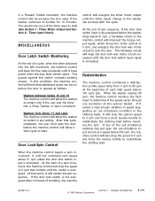
...Washers between Series 10 and 16 The machine control will allow the washer to redistribute the clothing load. When the washer reaches 85 rpm, the machine control monitors the Tach Input to stall (See Section 1: Timer Motor Output and Section 2: Timer Input Chart). Door Lock/Spin Control control will energize the timer motor... of tumbling, the machine 16008373-01 © 1998 Maytag Corporation SECTION 1. In a Prewash Tumble increment, the machine control will de-energize the line relay if the washer continues to redistribute the clothing load before resuming the spin.
...Washers between Series 10 and 16 The machine control will allow the washer to redistribute the clothing load. When the washer reaches 85 rpm, the machine control monitors the Tach Input to stall (See Section 1: Timer Motor Output and Section 2: Timer Input Chart). Door Lock/Spin Control control will energize the timer motor... of tumbling, the machine 16008373-01 © 1998 Maytag Corporation SECTION 1. In a Prewash Tumble increment, the machine control will de-energize the line relay if the washer continues to redistribute the clothing load before resuming the spin.
Service Manual
Page 18
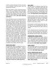
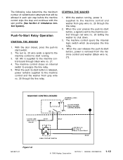
... . 3. 120 VAC is supplied to the machine control and washer from gray wire no. 26 through the line relay. 2. GENERAL INFORMATION 1-12 With the door closed ) GY 26 BK 27 PUSH TO START SWITCH 120 VAC Line To Timer & Motor Control Board RD 28 Figure 1-8 16008373-01 © 1998 Maytag Corporation SECTION 1. The red no. 28...
... . 3. 120 VAC is supplied to the machine control and washer from gray wire no. 26 through the line relay. 2. GENERAL INFORMATION 1-12 With the door closed ) GY 26 BK 27 PUSH TO START SWITCH 120 VAC Line To Timer & Motor Control Board RD 28 Figure 1-8 16008373-01 © 1998 Maytag Corporation SECTION 1. The red no. 28...
Service Manual
Page 25
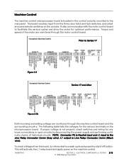
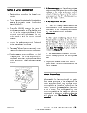
...and selector switches on the machine control. 16008373-01 SECTION 2. Prior to the rear panel. It also communicates with the motor control board to a wash cycle and press the start/off button. ELECTRICAL COMPONENTS & TESTING 2 - 5 © 1998 Maytag Corporation The board receives input ...check switches and wiring for the various terminals on the microprocessor board. Machine Control The machine control microprocessor board is located in the control console, mounted to Series 17 Figure 2-3 Series 17 and After Figure 2-3b Both incoming and exiting voltage are monitored through ...
...and selector switches on the machine control. 16008373-01 SECTION 2. Prior to the rear panel. It also communicates with the motor control board to a wash cycle and press the start/off button. ELECTRICAL COMPONENTS & TESTING 2 - 5 © 1998 Maytag Corporation The board receives input ...check switches and wiring for the various terminals on the microprocessor board. Machine Control The machine control microprocessor board is located in the control console, mounted to Series 17 Figure 2-3 Series 17 and After Figure 2-3b Both incoming and exiting voltage are monitored through ...
Service Manual
Page 27
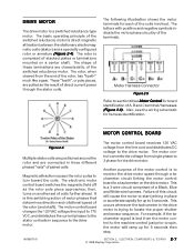
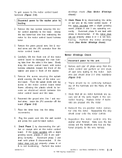
... of stacked plates or laminations mounted on another set of the motor control is trying to 5 seconds. The electronic motor control board switches the magnetic field off as the result of the rotor, has "teeth" much like a gear. ELECTRICAL COMPONENTS & TESTING 2 - 7 © 1998 Maytag Corporation MOTOR CONTROL BOARD Figure 2-4 Multiple stator coils are positioned around the rotor...
... of stacked plates or laminations mounted on another set of the motor control is trying to 5 seconds. The electronic motor control board switches the magnetic field off as the result of the rotor, has "teeth" much like a gear. ELECTRICAL COMPONENTS & TESTING 2 - 7 © 1998 Maytag Corporation MOTOR CONTROL BOARD Figure 2-4 Multiple stator coils are positioned around the rotor...
Service Manual
Page 28
... the motor. ELECTRICAL COMPONENTS & TESTING 2 - 8 © 1998 Maytag Corporation If the motor does not run under light loads when one of the phases of phase. Check the 10-amp fuse located on front end of the motor and motor control circuit. Unplug the washer power cord and replace motor control board connector JP4 when finished. Unplug the washer power cord. The motor control will...
... the motor. ELECTRICAL COMPONENTS & TESTING 2 - 8 © 1998 Maytag Corporation If the motor does not run under light loads when one of the phases of phase. Check the 10-amp fuse located on front end of the motor and motor control circuit. Unplug the washer power cord and replace motor control board connector JP4 when finished. Unplug the washer power cord. The motor control will...
Service Manual
Page 29
... cover onto the motor control. 8. Leave the JP4 connector off the board (Figure 2-6). 7 . Place the timer knob into the washer when finished. Motor Windings Check 1 . There should show 2-3 ohms resistance (Figure 2-5). 2. Perform the motor 5. ELECTRICAL COMPONENTS & TESTING © 1998 Maytag Corporation 2-9 Reconnect...front of the motor control board. Remove the screw securing the splash shield covering the face of the washer. 5. Reposition the motor control into the delay increments. 10. To gain access to the motor. Perform the motor windings check (See Motor ...
... cover onto the motor control. 8. Leave the JP4 connector off the board (Figure 2-6). 7 . Place the timer knob into the washer when finished. Motor Windings Check 1 . There should show 2-3 ohms resistance (Figure 2-5). 2. Perform the motor 5. ELECTRICAL COMPONENTS & TESTING © 1998 Maytag Corporation 2-9 Reconnect...front of the motor control board. Remove the screw securing the splash shield covering the face of the washer. 5. Reposition the motor control into the delay increments. 10. To gain access to the motor. Perform the motor windings check (See Motor ...
Service Manual
Page 30
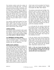
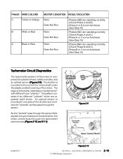
...the sensor. Figure 2-9 16008373-01 Figure 2-10 SECTION 2. PHASE WIRE COLORS C Yellow or Orange B White or Red A Black or Blue MOTOR CONDITION RESULT/SOLUTION Runs Does Not Run Runs Does Not Run Runs Does Not Run -Phases A&B are operating correctly. (Check Phase A and B)...functional. (See Step 10) Tachometer Circuit Diagnostics The tachometer system of the motor is comprised of the motor. ELECTRICAL COMPONENTS & TESTING 2-10 © 1998 Maytag Corporation An optical sensor is mounted to the motor control board through the tachometer wire harness (Figure 2-10 and 2-11). The edge...
...the sensor. Figure 2-9 16008373-01 Figure 2-10 SECTION 2. PHASE WIRE COLORS C Yellow or Orange B White or Red A Black or Blue MOTOR CONDITION RESULT/SOLUTION Runs Does Not Run Runs Does Not Run Runs Does Not Run -Phases A&B are operating correctly. (Check Phase A and B)...functional. (See Step 10) Tachometer Circuit Diagnostics The tachometer system of the motor is comprised of the motor. ELECTRICAL COMPONENTS & TESTING 2-10 © 1998 Maytag Corporation An optical sensor is mounted to the motor control board through the tachometer wire harness (Figure 2-10 and 2-11). The edge...
Service Manual
Page 31
... washer into the back side of the connections on both ends. Figure 2-11 The motor control monitors the signals and communicates this signal is comprised of the tachometer harness between the motor and motor control board. The purpose of this information to Black (From Motor Control) 11 VDC (± 2.5 VDC) Good Motor Control Board White To Black (From Motor 0 VDC Control) Bad Motor Control...
... washer into the back side of the connections on both ends. Figure 2-11 The motor control monitors the signals and communicates this signal is comprised of the tachometer harness between the motor and motor control board. The purpose of this information to Black (From Motor Control) 11 VDC (± 2.5 VDC) Good Motor Control Board White To Black (From Motor 0 VDC Control) Bad Motor Control...
Service Manual
Page 35
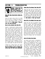
... the machine control board. If lower, the customer can use smaller clothes loads and reduce the pressure to prevent flooding in the button of the door lock mechanism is done through the door lock enable switch. SECTION 3. TROUBLESHOOTING Warning - Check the motor and motor control system by...-01 © 1998 Maytag Corporation SECTION 3. This is the RD 30 wire leading from the motor control to metal screened washers and remove the nozzle extender found in the door lock wax motor. If the machine control board does not see a return signal, the washer will open the line relay...
... the machine control board. If lower, the customer can use smaller clothes loads and reduce the pressure to prevent flooding in the button of the door lock mechanism is done through the door lock enable switch. SECTION 3. TROUBLESHOOTING Warning - Check the motor and motor control system by...-01 © 1998 Maytag Corporation SECTION 3. This is the RD 30 wire leading from the motor control to metal screened washers and remove the nozzle extender found in the door lock wax motor. If the machine control board does not see a return signal, the washer will open the line relay...
Service Manual
Page 72
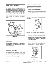
... tub mounting pad (Figure 7-11). Remove the two bolts securing the weight to the unit. 2. Lower the front weight and guard against hitting the motor control microprocessor board mounted to the bottom of the outer tub assembly. NOTE: The bolts screw into two nuts below the... tub. Front Weight Two counter weights are not repairable or replaceable. OUTER TUB ASSEMBLY The outer tub assembly is required. Lift top cover (See Top Cover). 3. OUTER TUB & SPINNER ASSEMBLY © 1998 Maytag Corporation 7-7 REMOVAL OF UPPER WEIGHT 1. One...
... tub mounting pad (Figure 7-11). Remove the two bolts securing the weight to the unit. 2. Lower the front weight and guard against hitting the motor control microprocessor board mounted to the bottom of the outer tub assembly. NOTE: The bolts screw into two nuts below the... tub. Front Weight Two counter weights are not repairable or replaceable. OUTER TUB ASSEMBLY The outer tub assembly is required. Lift top cover (See Top Cover). 3. OUTER TUB & SPINNER ASSEMBLY © 1998 Maytag Corporation 7-7 REMOVAL OF UPPER WEIGHT 1. One...

Service Manual
Page 76
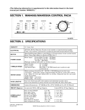
...the adjustment number aligned with the face of the motor pulley. MOTOR DRIVE SYSTEM © 1998 Maytag Corporation 8-1 A slot in a clockwise rotation. Disconnect power to the drive system, such as the drive motor, drive belt, motor control, machine control and accelerometer switch. If loose, remove the belt... toward the inside (Figure 8-1). 1 . Remove the front panel, rear access panel and the front weight (See Front Panel & Rear Access Removal). 3 . The belt encircles the motor pulley and the drive pulley of the outer tub. MOTOR DRIVE SYSTEM Warning - Always shut off the drive pulley...
...the adjustment number aligned with the face of the motor pulley. MOTOR DRIVE SYSTEM © 1998 Maytag Corporation 8-1 A slot in a clockwise rotation. Disconnect power to the drive system, such as the drive motor, drive belt, motor control, machine control and accelerometer switch. If loose, remove the belt... toward the inside (Figure 8-1). 1 . Remove the front panel, rear access panel and the front weight (See Front Panel & Rear Access Removal). 3 . The belt encircles the motor pulley and the drive pulley of the outer tub. MOTOR DRIVE SYSTEM Warning - Always shut off the drive pulley...
Service Manual
Page 78
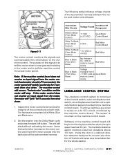
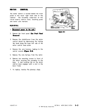
Disconnect power to the control console (Figure 8-4). 5 . Remove the front panel (See Front Panel Removal). 3 . Remove the shield/cover from the motor. 6 . Figure 8-4 16008373-01 SECTION 8. MOTOR DRIVE SYSTEM © 1998 Maytag Corporation 8-3 To replace, reverse the previous steps. MOTOR CONTROL The motor control is located behind the front panel in the base frame. 7 . Remove the wire harness leading to the unit...
Disconnect power to the control console (Figure 8-4). 5 . Remove the front panel (See Front Panel Removal). 3 . Remove the shield/cover from the motor. 6 . Figure 8-4 16008373-01 SECTION 8. MOTOR DRIVE SYSTEM © 1998 Maytag Corporation 8-3 To replace, reverse the previous steps. MOTOR CONTROL The motor control is located behind the front panel in the base frame. 7 . Remove the wire harness leading to the unit...
Service Manual
Page 89
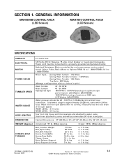
...inlet hoses with inlet washers and attached to a properly grounded and polarized outlet. Cabinet Dimensions: 27" (68.58cm) ... Spin Pulley Bolt, Belt Adjuster Screw, Front Baffle Screw, Rear Baffle Clamp, Hoses Nuts...motor control board. lbs. 30 in . lbs. 18.5 in . Total water usage is supplemental to the information found in . lbs. 15 + in . SPECIFICATIONS CAPACITY ELECTRICAL MOTOR POWER USAGE TUMBLER SPEED WATER USAGE HOSE LENGTHS DIMENSIONS 3.1 Cubic Feet 120 Volts, 60 Hz; (The following information is approximately 25 gallons, varies with clothes load. MAH4000/MAH5500A CONTROL...
...inlet hoses with inlet washers and attached to a properly grounded and polarized outlet. Cabinet Dimensions: 27" (68.58cm) ... Spin Pulley Bolt, Belt Adjuster Screw, Front Baffle Screw, Rear Baffle Clamp, Hoses Nuts...motor control board. lbs. 30 in . lbs. 18.5 in . Total water usage is supplemental to the information found in . lbs. 15 + in . SPECIFICATIONS CAPACITY ELECTRICAL MOTOR POWER USAGE TUMBLER SPEED WATER USAGE HOSE LENGTHS DIMENSIONS 3.1 Cubic Feet 120 Volts, 60 Hz; (The following information is approximately 25 gallons, varies with clothes load. MAH4000/MAH5500A CONTROL...
Service Manual
Page 95
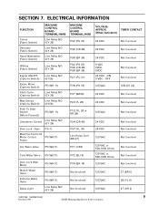
... - Spin P3 (1) Machine Control & Motor Control P5 (WH11) Power Hot Water Valve P5 (WH11) Cold Water Valve P5 (WH11) Door Lock Wax Motor Bleach Water Valve Softener Water Valve Delay Light P5 (WH11) P5 (WH11) P5 (WH11) Line Relay NO (GY 26) MACHINE CONTROL BOARD TERMINAL/WIRE P3/2 ...120 VAC 4T (OR 2) 16010199 (16008373-03) 8 Revised 7/00 ©2000 Maytag Appliances Sales Company SECTION 7. ELECTRICAL INFORMATION FUNCTION Colors (Fabric Switch) Delicates (Fabric Switch) Hand Washables (Fabric Switch) MACHINE CONTROL BOARD TERMINAL/WIRE Line Relay NO (GY 26) Line Relay NO (GY 26)...
... - Spin P3 (1) Machine Control & Motor Control P5 (WH11) Power Hot Water Valve P5 (WH11) Cold Water Valve P5 (WH11) Door Lock Wax Motor Bleach Water Valve Softener Water Valve Delay Light P5 (WH11) P5 (WH11) P5 (WH11) Line Relay NO (GY 26) MACHINE CONTROL BOARD TERMINAL/WIRE P3/2 ...120 VAC 4T (OR 2) 16010199 (16008373-03) 8 Revised 7/00 ©2000 Maytag Appliances Sales Company SECTION 7. ELECTRICAL INFORMATION FUNCTION Colors (Fabric Switch) Delicates (Fabric Switch) Hand Washables (Fabric Switch) MACHINE CONTROL BOARD TERMINAL/WIRE Line Relay NO (GY 26) Line Relay NO (GY 26)...
Service Manual
Page 109
...Motor Pulley Ratio (Motor to Spinner RPM) 14 to 1 (MAH5500B) 14.1 to a properly grounded and polarized outlet. LCD Washer (MAH7500A) Water pressure should be connected to 1 (MAH7500A) Motor...load. lbs. 38 ft.lbs. 22 ft. Switched Reluctance Motor controlled by a microprocessor motor control board. Bolt, Counter Weight Bolt, Spin Pulley Bolt, Belt Adjuster Screw, Front... water usage is approximately 25 gallons, varies with no clothes in . Cabinet Dimensions: 27" (68.58cm) W x 271/2" (69.85cm) D x 36" (91...spin performance) LED Washer (MAH5500B) 1000 RPM No tuning of the spin ...
...Motor Pulley Ratio (Motor to Spinner RPM) 14 to 1 (MAH5500B) 14.1 to a properly grounded and polarized outlet. LCD Washer (MAH7500A) Water pressure should be connected to 1 (MAH7500A) Motor...load. lbs. 38 ft.lbs. 22 ft. Switched Reluctance Motor controlled by a microprocessor motor control board. Bolt, Counter Weight Bolt, Spin Pulley Bolt, Belt Adjuster Screw, Front... water usage is approximately 25 gallons, varies with no clothes in . Cabinet Dimensions: 27" (68.58cm) W x 271/2" (69.85cm) D x 36" (91...spin performance) LED Washer (MAH5500B) 1000 RPM No tuning of the spin ...


