Network Users Manual - English
Page 13
... advanced management of Brother network management tools to locally connected machines. Unlike BRAdmin Professional 3, which then communicates with the ability to monitor Brother printer's status or change some of brother devices on your network...or greater. For more information and to check items such as page counts, toner and drum status and the firmware version. Web Based Management (web browser) 1 The Web Based Management...to a client PC via the USB or parallel interface from a MFC or DCP connected via the parallel or USB interface. This allows the administrator to...
... advanced management of Brother network management tools to locally connected machines. Unlike BRAdmin Professional 3, which then communicates with the ability to monitor Brother printer's status or change some of brother devices on your network...or greater. For more information and to check items such as page counts, toner and drum status and the firmware version. Web Based Management (web browser) 1 The Web Based Management...to a client PC via the USB or parallel interface from a MFC or DCP connected via the parallel or USB interface. This allows the administrator to...
Users Manual - English
Page 142
... Start button, Control Panel, Hardware and Sound, and then Printers. Right-click Brother MFC-XXXX Printer. Black vertical lines on copies are installed properly. (See Replacing the drum unit on page 163.) „ Check the interface cable connection on page 139.) „ Check that the correct printer driver has been installed and chosen. „ Check to...
... Start button, Control Panel, Hardware and Sound, and then Printers. Right-click Brother MFC-XXXX Printer. Black vertical lines on copies are installed properly. (See Replacing the drum unit on page 163.) „ Check the interface cable connection on page 139.) „ Check that the correct printer driver has been installed and chosen. „ Check to...
Users Manual - English
Page 147
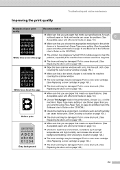
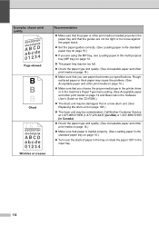
...sure that you choose the appropriate media type in the printer driver or in the machine's Paper Type menu setting. (See Acceptable abcde 01234 paper and other print media on page 14 and Basic tab in a new drum unit. (See Replacing the drum unit on page 163.) ABCDEFGH abcdefghijk ABCD abcde 01234... White lines down the page „ Wipe the laser scanner windows with a dry, lint-free soft cloth. (See Cleaning the laser scanner window on page 154.) „ Make sure...
...sure that you choose the appropriate media type in the printer driver or in the machine's Paper Type menu setting. (See Acceptable abcde 01234 paper and other print media on page 14 and Basic tab in a new drum unit. (See Replacing the drum unit on page 163.) ABCDEFGH abcdefghijk ABCD abcde 01234... White lines down the page „ Wipe the laser scanner windows with a dry, lint-free soft cloth. (See Cleaning the laser scanner window on page 154.) „ Make sure...
Users Manual - English
Page 148
...-276-8437) (in USA) or 1-877-BROTHER (in Canada). „ Check the paper type and quality. (See Acceptable paper and other ...the Software User's Guide on page 14.) „ Make sure that meets our specifications. Put in a new drum unit. (See Replacing the drum unit on page 163.) „ The fuser unit may cause the problem. (See Acceptable paper and other print...that you choose the proper media type in the printer driver or in the machine's Paper Type menu setting. (See Acceptable paper and other print media on the CD-ROM.) „ The drum unit may be contaminated. Examples of paper in ...
...-276-8437) (in USA) or 1-877-BROTHER (in Canada). „ Check the paper type and quality. (See Acceptable paper and other ...the Software User's Guide on page 14.) „ Make sure that meets our specifications. Put in a new drum unit. (See Replacing the drum unit on page 163.) „ The fuser unit may cause the problem. (See Acceptable paper and other print...that you choose the proper media type in the printer driver or in the machine's Paper Type menu setting. (See Acceptable paper and other print media on the CD-ROM.) „ The drum unit may be contaminated. Examples of paper in ...
Users Manual - English
Page 151
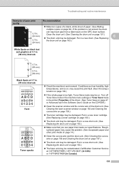
.... (See Cleaning the laser scanner window on page 154 and Cleaning the corona wire on page 163.) „ The fuser unit may be contaminated. Turn off Toner Save mode in the machine menu settings or Toner Save mode in the printer Properties of the driver. (See Toner Save on page 27 or... page 84.) If the problem is too light, Toner Save mode may be on page 157.) „ The drum unit may be damaged. Call Brother Customer Service at 3.7 in a new drum. (See Replacing the drum unit on page 163.) White Spots on page 163.) „ Make sure that you use paper that meets our...
.... (See Cleaning the laser scanner window on page 154 and Cleaning the corona wire on page 163.) „ The fuser unit may be contaminated. Turn off Toner Save mode in the machine menu settings or Toner Save mode in the printer Properties of the driver. (See Toner Save on page 27 or... page 84.) If the problem is too light, Toner Save mode may be on page 157.) „ The drum unit may be damaged. Call Brother Customer Service at 3.7 in a new drum. (See Replacing the drum unit on page 163.) White Spots on page 163.) „ Make sure that you use paper that meets our...
Users Manual - English
Page 210
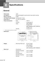
... E Printer Type Laser Print Method Electrophotography by semiconductor laser beam scanning Memory Capacity 64 MB LCD (liquid crystal display) 22 characters × 5 lines Power Source 110-120 V AC 50/60 Hz Power Consumption Peak: 1080 W Copying: Average 680 W 1 Sleep: (MFC-8480DN) Average 18 W (MFC-8680DN and MFC-8890DW) Average 19 W Standby: Average 85 W 1 When making a copy from one...
... E Printer Type Laser Print Method Electrophotography by semiconductor laser beam scanning Memory Capacity 64 MB LCD (liquid crystal display) 22 characters × 5 lines Power Source 110-120 V AC 50/60 Hz Power Consumption Peak: 1080 W Copying: Average 680 W 1 Sleep: (MFC-8480DN) Average 18 W (MFC-8680DN and MFC-8890DW) Average 19 W Standby: Average 85 W 1 When making a copy from one...
Service Manual
Page 39
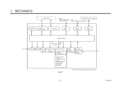
...Centronics parallel interface USB interface WLAN PCB LAN interface USB interface Line Control Section Fax data Printer data NCU* Speaker ADF unit Scanner unit Laser printing unit Paper Low- ADF motor - CCD motor Charging, exposing, developing, transferring, and... feeding mechanism high-voltage power supplies AC heat-fixing processes - Transfer roller - and - Laser-sensitive drum - Laser unit (including the polygon motor) -...
...Centronics parallel interface USB interface WLAN PCB LAN interface USB interface Line Control Section Fax data Printer data NCU* Speaker ADF unit Scanner unit Laser printing unit Paper Low- ADF motor - CCD motor Charging, exposing, developing, transferring, and... feeding mechanism high-voltage power supplies AC heat-fixing processes - Transfer roller - and - Laser-sensitive drum - Laser unit (including the polygon motor) -...
Service Manual
Page 41
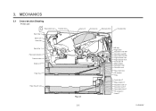
MECHANICS 3.1 Cross-section Drawing - Printer part Paper stack lever Transfer roller Eject roller 2 Back cover Heat roller Eject roller 1 Paper eject actuator Pressure roller Duplex unit Paper tray Paper tray (LT unit) Laser unit Corona wire Exposure drum Develop roller Fig. 2-3 2-3 MP tray Regist roller Separation rollerMMPP Separation pad MP Paper feed roller MP...
MECHANICS 3.1 Cross-section Drawing - Printer part Paper stack lever Transfer roller Eject roller 2 Back cover Heat roller Eject roller 1 Paper eject actuator Pressure roller Duplex unit Paper tray Paper tray (LT unit) Laser unit Corona wire Exposure drum Develop roller Fig. 2-3 2-3 MP tray Regist roller Separation rollerMMPP Separation pad MP Paper feed roller MP...

Service Manual
Page 54
The printer starts transferring an image when a definite time passes after the paper is fed to the transfer roller controls the first print position on , the regist ... roller, is fed further for a specified time, and the paper top position reaches the regist roller so that the paper skew is adjusted. Drum/toner ASSY Exposure drum Transfer roller Regist actuator rear Regist roller Regist actuator front Fig. 2-16 Separation roller The regist actuator rear in the path from the regist...
The printer starts transferring an image when a definite time passes after the paper is fed to the transfer roller controls the first print position on , the regist ... roller, is fed further for a specified time, and the paper top position reaches the regist roller so that the paper skew is adjusted. Drum/toner ASSY Exposure drum Transfer roller Regist actuator rear Regist roller Regist actuator front Fig. 2-16 Separation roller The regist actuator rear in the path from the regist...
Service Manual
Page 82
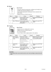
...home position sensor to USB device 3-29 CA 3-35 A4 ADF cover opened (Not applicable) 3-29 CD Drum unit is not turned on. at High side 3-32 8A Paper jam in MP Tray 3-26 BB White...detection lever failure 3-34 9F Paper empty 3-28 C7 Run out of memory for data expansion of PC printer 3-34 A1 Front cover opened 3-28 C8 Secure print data full 3-34 A2 During scanning, 90 cm... temperature of heat 3-30 DE roller detected the temperature 3-36 that was lower than twice the standard Drum Life.) 84 Paper jam 3-24 AF CCD unit home position sensor is not turned off. 3-31 85...
...home position sensor to USB device 3-29 CA 3-35 A4 ADF cover opened (Not applicable) 3-29 CD Drum unit is not turned on. at High side 3-32 8A Paper jam in MP Tray 3-26 BB White...detection lever failure 3-34 9F Paper empty 3-28 C7 Run out of memory for data expansion of PC printer 3-34 A1 Front cover opened 3-28 C8 Secure print data full 3-34 A2 During scanning, 90 cm... temperature of heat 3-30 DE roller detected the temperature 3-36 that was lower than twice the standard Drum Life.) 84 Paper jam 3-24 AF CCD unit home position sensor is not turned off. 3-31 85...
Service Manual
Page 119
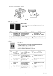
...the toner cartridge with a new one . Yes Replace the drum unit. ■ Dark - Replace the drum unit with a new one . - Drum unit failure Is the problem solved Replace the drum unit. Main PCB failure Is the problem solved after replacing the drum Yes unit? Result Remedy Re-...ASSY. 3-47 Confidential ■ Faulty registration Fig. 3-6 - Check that the appropriate media type is selected in the printer driver. Developing bias Is the problem solved Reset the developer roller malfunciton after replacing the HVPS PCB ASSY? Replace the HVPS PCB...
...the toner cartridge with a new one . Yes Replace the drum unit. ■ Dark - Replace the drum unit with a new one . - Drum unit failure Is the problem solved Replace the drum unit. Main PCB failure Is the problem solved after replacing the drum Yes unit? Result Remedy Re-...ASSY. 3-47 Confidential ■ Faulty registration Fig. 3-6 - Check that the appropriate media type is selected in the printer driver. Developing bias Is the problem solved Reset the developer roller malfunciton after replacing the HVPS PCB ASSY? Replace the HVPS PCB...
Service Manual
Page 125
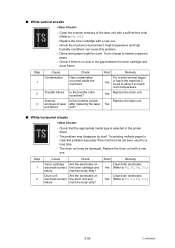
... - ■ White vertical streaks - Is the problem solved after replacing the laser unit? Check that the appropriate media type is no dust in the printer driver. - Replace the drum unit with a new one . High temperature and high humidity conditions can cause this problem especially if the ...machine has not been used . Drum unit Are the electrodes on electrode contact the toner ...
... - ■ White vertical streaks - Is the problem solved after replacing the laser unit? Check that the appropriate media type is no dust in the printer driver. - Replace the drum unit with a new one . High temperature and high humidity conditions can cause this problem especially if the ...machine has not been used . Drum unit Are the electrodes on electrode contact the toner ...
Service Manual
Page 130
...Replace the toner cartridge with a new one. - Replace the drum unit with a new one . HVPS PCB failure Is the problem solved after replacing the HVPS PCB ASSY? CAUTION : • This problem often occurs when the drum unit or toner cartridge is selected in the printer driver. - ■ Ghost - ...Yes ASSY. Check the machine's environment, conditions such as high or low humidity may cause this situation to occur. - Replace the drum unit with a new one . - Replace the main PCB Yes ASSY. ■ Fogging - Main PCB failure Is the problem solved after replacing the main ...
...Replace the toner cartridge with a new one. - Replace the drum unit with a new one . HVPS PCB failure Is the problem solved after replacing the HVPS PCB ASSY? CAUTION : • This problem often occurs when the drum unit or toner cartridge is selected in the printer driver. - ■ Ghost - ...Yes ASSY. Check the machine's environment, conditions such as high or low humidity may cause this situation to occur. - Replace the drum unit with a new one . - Replace the main PCB Yes ASSY. ■ Fogging - Main PCB failure Is the problem solved after replacing the main ...
Service Manual
Page 153
... Does the machine print test pattern? (Check it following the procedure described in "4.5 Test Pattern 1 (Function code 09)" in Library/ Printers, and that the printer driver which is not detected. Step 1 2 Cause USB host PCB failure Main PCB failure Remedy Replace the USB host PCB. Make sure... correct movement of this chapter. Check that the print queue is created. - New toner actuator damaged Replace the drum unit. Main PCB ...
... Does the machine print test pattern? (Check it following the procedure described in "4.5 Test Pattern 1 (Function code 09)" in Library/ Printers, and that the printer driver which is not detected. Step 1 2 Cause USB host PCB failure Main PCB failure Remedy Replace the USB host PCB. Make sure... correct movement of this chapter. Check that the print queue is created. - New toner actuator damaged Replace the drum unit. Main PCB ...
Service Manual
Page 158
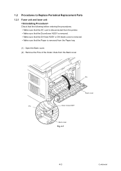
Pin Back cover Pin Outer chute ASSY Back cover Fig. 4-1 4-3 Confidential 1.2 Procedures to Replace Periodical Replacement Parts 1.2.1 Fuser unit and laser unit Check that the following before entering the procedures. • Make sure that the AC cord is disconnected from the printer. • Make sure that the Drum/toner ASSY is removed. • Make sure that the DX feed ASSY or DX blank cover is removed. • Make sure that the Paper is removed from the Paper tray. (1) Open the Back cover. (2) Remove the Pins of the Outer chute from the Back cover.
Pin Back cover Pin Outer chute ASSY Back cover Fig. 4-1 4-3 Confidential 1.2 Procedures to Replace Periodical Replacement Parts 1.2.1 Fuser unit and laser unit Check that the following before entering the procedures. • Make sure that the AC cord is disconnected from the printer. • Make sure that the Drum/toner ASSY is removed. • Make sure that the DX feed ASSY or DX blank cover is removed. • Make sure that the Paper is removed from the Paper tray. (1) Open the Back cover. (2) Remove the Pins of the Outer chute from the Back cover.

Service Manual
Page 184
(30) Catch the Pins of the Outer chute onto the Back cover, and close the Back cover. 30b Pin Back cover Pin Outer chute ASSY 30a Back cover Fig. 4-44 Set the following parts after assembling. • Set the DX feed ASSY or DX blank cover. • Install the Drum/toner ASSY into the Printer. • Put the Paper into the Paper tray. • Reset the count of the Fuser unit and Laser unit after part replacement. (Refer to "5.1 Resetting the Periodical Replacement Parts Life" in Chapter7.) 4-29 Confidential
(30) Catch the Pins of the Outer chute onto the Back cover, and close the Back cover. 30b Pin Back cover Pin Outer chute ASSY 30a Back cover Fig. 4-44 Set the following parts after assembling. • Set the DX feed ASSY or DX blank cover. • Install the Drum/toner ASSY into the Printer. • Put the Paper into the Paper tray. • Reset the count of the Fuser unit and Laser unit after part replacement. (Refer to "5.1 Resetting the Periodical Replacement Parts Life" in Chapter7.) 4-29 Confidential
Service Manual
Page 185
... tray 1, 2 < Uninstalling Procedure > Check that the following before entering the procedures. • Make sure that the AC cord is disconnected from the printer. • Make sure that the Drum/toner ASSY is removed. • Make sure that the DX feed ASSY or DX blank cover is removed. • Make sure that the...
... tray 1, 2 < Uninstalling Procedure > Check that the following before entering the procedures. • Make sure that the AC cord is disconnected from the printer. • Make sure that the Drum/toner ASSY is removed. • Make sure that the DX feed ASSY or DX blank cover is removed. • Make sure that the...
Service Manual
Page 189
Lift arm Pin Roller holder ASSY Paper feed frame 2a 2b Fig. 4-49 (4) Install the DX feed ASSY or DX blank cover, and install the Drum/toner ASSY. 4-34 Confidential (2) Assemble the Lift arm onto the Pin of the Roller holder ASSY. (3) Place the Printer on its base.
Lift arm Pin Roller holder ASSY Paper feed frame 2a 2b Fig. 4-49 (4) Install the DX feed ASSY or DX blank cover, and install the Drum/toner ASSY. 4-34 Confidential (2) Assemble the Lift arm onto the Pin of the Roller holder ASSY. (3) Place the Printer on its base.
Service Manual
Page 191
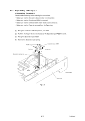
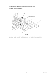
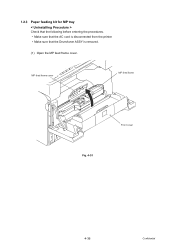
1.2.3 Paper feeding kit for MP tray < Uninstalling Procedure > Check that the following before entering the procedures. • Make sure that the AC cord is disconnected from the printer. • Make sure that the Drum/toner ASSY is removed. (1) Open the MP feed frame cover. MP feed frame cover MP feed frame Front cover Fig. 4-51 4-36 Confidential
1.2.3 Paper feeding kit for MP tray < Uninstalling Procedure > Check that the following before entering the procedures. • Make sure that the AC cord is disconnected from the printer. • Make sure that the Drum/toner ASSY is removed. (1) Open the MP feed frame cover. MP feed frame cover MP feed frame Front cover Fig. 4-51 4-36 Confidential

Service Manual
Page 195
MP feed frame cover MP feed frame MP feed frame Front cover Fig. 4-58 (5) Install the Drum/toner ASSY into the MP feed frame and turn the Holder bearing MP to lock. (3) Put the Holder bearing MP into the Printer. (6) Close the Front cover. * Reset the count of the arrow 3c to the direction of the PF Kit MP after part replacement. 4-40 Confidential Holder bearing MP Hook 3a 3c 3b Fig. 4-57 (4) Close the MP feed frame cover.
MP feed frame cover MP feed frame MP feed frame Front cover Fig. 4-58 (5) Install the Drum/toner ASSY into the MP feed frame and turn the Holder bearing MP to lock. (3) Put the Holder bearing MP into the Printer. (6) Close the Front cover. * Reset the count of the arrow 3c to the direction of the PF Kit MP after part replacement. 4-40 Confidential Holder bearing MP Hook 3a 3c 3b Fig. 4-57 (4) Close the MP feed frame cover.


