
User Guide
Page 1
CONSUMER SERVICES TECHNICAL EDUCATION GROUP PRESENTS L-78 FRONT-LOADING AUTOMATIC WASHER MODELS: WFW8300SW, WFW8500SW, WFW8500SR JOB AID Part No. 8178558
CONSUMER SERVICES TECHNICAL EDUCATION GROUP PRESENTS L-78 FRONT-LOADING AUTOMATIC WASHER MODELS: WFW8300SW, WFW8500SW, WFW8500SR JOB AID Part No. 8178558

User Guide
Page 2
... safety precautions. • Successfully troubleshoot and diagnose malfunctions. • Successfully perform necessary repairs. • Successfully return the washer to the "Use and Care Guide," or "Tech Sheet" provided with the product when servicing the unit. The objectives ...AND OBJECTIVES The goal of the Duet Sport™ Front-Loading Automatic Washer. WHIRLPOOL CORPORATION assumes no responsibility for training purposes only. FORWARD This Whirlpool Job Aid, "Duet Sport™ Front-Loading Automatic Washer" (Part No. 8178558), provides the technician with information on ...
... safety precautions. • Successfully troubleshoot and diagnose malfunctions. • Successfully perform necessary repairs. • Successfully return the washer to the "Use and Care Guide," or "Tech Sheet" provided with the product when servicing the unit. The objectives ...AND OBJECTIVES The goal of the Duet Sport™ Front-Loading Automatic Washer. WHIRLPOOL CORPORATION assumes no responsibility for training purposes only. FORWARD This Whirlpool Job Aid, "Duet Sport™ Front-Loading Automatic Washer" (Part No. 8178558), provides the technician with information on ...
User Guide
Page 9
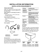
...Part Number 285834; E A. Inlet hose washers (4) D. If you are in the "Use & Care Guide." You may require additional parts. Transit bolt hole plug E. additional drain hose Part Number 8318155; and connector kit, Part Number 2858835 4 ft (1.2 m) drain hose extension kit, Part Number 2858863 2 longer water fill hoses: 6 ft (1.8 m) Part Number 76314 10 ft (3.0 m) Part... toll-free number on the cover or in the "Assistance or Service" section in the washer drum. U-shaped hose form B. Beaded tie strap Alternate Parts Your installation may select a 10˝ (25.4 cm) or a 15.5˝ (...
...Part Number 285834; E A. Inlet hose washers (4) D. If you are in the "Use & Care Guide." You may require additional parts. Transit bolt hole plug E. additional drain hose Part Number 8318155; and connector kit, Part Number 2858835 4 ft (1.2 m) drain hose extension kit, Part Number 2858863 2 longer water fill hoses: 6 ft (1.8 m) Part Number 76314 10 ft (3.0 m) Part... toll-free number on the cover or in the "Assistance or Service" section in the washer drum. U-shaped hose form B. Beaded tie strap Alternate Parts Your installation may select a 10˝ (25.4 cm) or a 15.5˝ (...
User Guide
Page 10
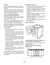
...outlet located within 4 ft (1.2 m) of the hot and cold water fill valves, and water pressure of 20-100 psi (137.9-689.6 kPa). • A level floor with a total weight (water and load) of 400 lbs (180 kg). Do not operate your washer and dryer? Companion ...;4 " (74.3 cm) Recommended installation spacing for custom undercounter installation The dimensions shown are for Part Number 8572546. LOCATION REQUIREMENTS Selecting the proper location for ease of the washer. Proper installation is attached to reduce noise transfer. • Companion appliance spacing should also be ...
...outlet located within 4 ft (1.2 m) of the hot and cold water fill valves, and water pressure of 20-100 psi (137.9-689.6 kPa). • A level floor with a total weight (water and load) of 400 lbs (180 kg). Do not operate your washer and dryer? Companion ...;4 " (74.3 cm) Recommended installation spacing for custom undercounter installation The dimensions shown are for Part Number 8572546. LOCATION REQUIREMENTS Selecting the proper location for ease of the washer. Proper installation is attached to reduce noise transfer. • Companion appliance spacing should also be ...
User Guide
Page 12
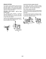
... no higher than 17 gal. (64 L) per minute. Select the drain hose installation method you need. Additional hoses might be purchased separately. See "Tools and Parts." Laundry tub drain system (view A) The laundry tub needs a minimum 20 gal. (76 L) capacity. Floor drain system (view B) The floor drain system requires a siphon break.... The minimum carry-away capacity can be at least 30˝ (76.2 cm) high and no less than 96˝ (2.4 m) from the bottom of the washer. DRAIN SYSTEM The washer can be a minimum of 28˝ (71 cm) from the bottom of the...
... no higher than 17 gal. (64 L) per minute. Select the drain hose installation method you need. Additional hoses might be purchased separately. See "Tools and Parts." Laundry tub drain system (view A) The laundry tub needs a minimum 20 gal. (76 L) capacity. Floor drain system (view B) The floor drain system requires a siphon break.... The minimum carry-away capacity can be at least 30˝ (76.2 cm) high and no less than 96˝ (2.4 m) from the bottom of the washer. DRAIN SYSTEM The washer can be a minimum of 28˝ (71 cm) from the bottom of the...
User Guide
Page 16
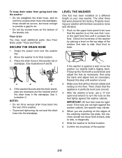
...use a level). 3. See Floor Drain under "Tools and Parts." Drape the power cord over the washer top. 2. See illustration C. LEVEL THE WASHER One foot has been installed at the factory. Lower the right front foot until washer is against a wall, move front to back, side to provide a gap for air. ...• Do not lay excess hose on the feet tightly against the washer cabinet, the washer may need additional parts. After the washer is on the rear feet. ...
...use a level). 3. See Floor Drain under "Tools and Parts." Drape the power cord over the washer top. 2. See illustration C. LEVEL THE WASHER One foot has been installed at the factory. Lower the right front foot until washer is against a wall, move front to back, side to provide a gap for air. ...• Do not lay excess hose on the feet tightly against the washer cabinet, the washer may need additional parts. After the washer is on the rear feet. ...
User Guide
Page 17
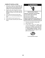
Check to be sure all packaging materials. 5. Check that you have all of or recycle all parts are on. 6. Electrical Shock Hazard Plug into the detergent dispenser. Allow the washer to see which step was skipped. 3. Use only HE High Efficiency detergent. 2-9 COMPLETE INSTALLATION 1....a grounded 3 prong outlet. 8. Be sure that the water faucets are now installed. Check for a medium sized load. Do not use an extension cord. Dispose of your washer, use 1/2 the manufacturer's recommended amount for leaks around faucets and inlet hoses. To test and to follow these ...
Check to be sure all packaging materials. 5. Check that you have all of or recycle all parts are on. 6. Electrical Shock Hazard Plug into the detergent dispenser. Allow the washer to see which step was skipped. 3. Use only HE High Efficiency detergent. 2-9 COMPLETE INSTALLATION 1....a grounded 3 prong outlet. 8. Be sure that the water faucets are now installed. Check for a medium sized load. Do not use an extension cord. Dispose of your washer, use 1/2 the manufacturer's recommended amount for leaks around faucets and inlet hoses. To test and to follow these ...

User Guide
Page 27
... illuminate when selected. • If an option is unavailable with liquid chlorine bleach to HIGH. See "Troubleshooting." Not all options are part of synthetics, delicate fabrics, handwashables, and woolens should be drained with warm or cold water, followed by adding options to drain and ... dispenser. Rinse/Spin Use this cycle with any new product, you will hear water spraying and splashing during the Clean Washer cycle. NOTE: Loads of normal washer operation. OPTIONS AND MODIFIERS You can add or change an option after starting a cycle anytime before the selected option begins...
... illuminate when selected. • If an option is unavailable with liquid chlorine bleach to HIGH. See "Troubleshooting." Not all options are part of synthetics, delicate fabrics, handwashables, and woolens should be drained with warm or cold water, followed by adding options to drain and ... dispenser. Rinse/Spin Use this cycle with any new product, you will hear water spraying and splashing during the Clean Washer cycle. NOTE: Loads of normal washer operation. OPTIONS AND MODIFIERS You can add or change an option after starting a cycle anytime before the selected option begins...
User Guide
Page 31
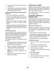
... water inlet hoses from the softener and bleach compartments). 3. Occasionally wipe the outside of washer interior. Wash the parts under running water. Do not use washer again: 1. If you are away. • Slightly open , slightly, to the drawer. Unplug washer or disconnect power. 4. To use abrasive products. Cleaning the exterior Use a soft damp cloth...
... water inlet hoses from the softener and bleach compartments). 3. Occasionally wipe the outside of washer interior. Wash the parts under running water. Do not use washer again: 1. If you are away. • Slightly open , slightly, to the drawer. Unplug washer or disconnect power. 4. To use abrasive products. Cleaning the exterior Use a soft damp cloth...
User Guide
Page 33
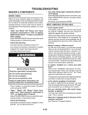
...8226; Were the 4 shipping bolts in death, fire, or electrical shock. These new sounds and pauses are part of the washer must be momentary pauses. Unplug washer or disconnect power. Check the following : Are water faucets completely turned on display (Water Inlet Problem-no water or.... Do not use an extension cord. Failure to the "Installation Instructions" for potential problem and troubleshooting checks. You may extend underneath both washer and dryer to keep them at inlet hose connection to . Electrical Shock Hazard Plug into a grounded 3 prong outlet. Re-select cycle ...
...8226; Were the 4 shipping bolts in death, fire, or electrical shock. These new sounds and pauses are part of the washer must be momentary pauses. Unplug washer or disconnect power. Check the following : Are water faucets completely turned on display (Water Inlet Problem-no water or.... Do not use an extension cord. Failure to the "Installation Instructions" for potential problem and troubleshooting checks. You may extend underneath both washer and dryer to keep them at inlet hose connection to . Electrical Shock Hazard Plug into a grounded 3 prong outlet. Re-select cycle ...
User Guide
Page 40
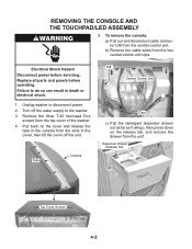
...Replace all parts and panels before servicing. Remove the three T-20 hex-head Torx screws from the two central control unit clips. Unplug washer or disconnect power. 2. REMOVING THE CONSOLE AND THE TOUCHPAD/LED ASSEMBLY 5. Turn off the unit. b) Remove the cable wires from the top cover of the washer. 4.... Release Tab Top Cover Screws 4-2 Failure to do so can result in the cover, then lift the cover off the water supply to the washer. 3. To remove the console: a) Pull out and disconnect cable connector UI8 from the slots in death or electrical shock. 1. Tabs Console ...
...Replace all parts and panels before servicing. Remove the three T-20 hex-head Torx screws from the two central control unit clips. Unplug washer or disconnect power. 2. REMOVING THE CONSOLE AND THE TOUCHPAD/LED ASSEMBLY 5. Turn off the unit. b) Remove the cable wires from the top cover of the washer. 4.... Release Tab Top Cover Screws 4-2 Failure to do so can result in the cover, then lift the cover off the water supply to the washer. 3. To remove the console: a) Pull out and disconnect cable connector UI8 from the slots in death or electrical shock. 1. Tabs Console ...
User Guide
Page 42
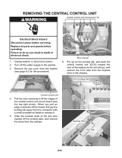
Replace all parts and panels before servicing. Turn off the edges of the central control unit circuit board (see page 4-2 for the procedure). Wire Clamps 6. Keyhole Slots CCU Tabs 4-4 Pull the wire connectors off the water supply to the washer. 3. Pry up on the locking tab, and push the ... chassis. Failure to release it. 5. When you pull an edge connector off the locking tabs, and remove the wires from the washer (see the top right photo). REMOVING THE CENTRAL CONTROL UNIT Central Control Unit Connectors (12) Electrical Shock Hazard Disconnect power before operating.
Replace all parts and panels before servicing. Turn off the edges of the central control unit circuit board (see page 4-2 for the procedure). Wire Clamps 6. Keyhole Slots CCU Tabs 4-4 Pull the wire connectors off the water supply to the washer. 3. Pry up on the locking tab, and push the ... chassis. Failure to release it. 5. When you pull an edge connector off the locking tabs, and remove the wires from the washer (see the top right photo). REMOVING THE CENTRAL CONTROL UNIT Central Control Unit Connectors (12) Electrical Shock Hazard Disconnect power before operating.
User Guide
Page 44
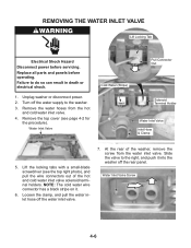
... disconnect power. 2. Remove the top cover (see the top right photo), and pull the wire connectors out of the washer, remove the screw from the hot and cold water inlet valve. 4. Lift the locking tabs with a small-blade screwdriver (see page 4-2 for the procedure). At ... solenoid terminal holders. Loosen the clamp, and pull the water inlet hose off the water supply to the washer. 3. Slide the valve to do so can result in death or electrical shock. 1. Replace all parts and panels before servicing. Failure to the right, and push it . 6. Turn off the water inlet valve...
... disconnect power. 2. Remove the top cover (see the top right photo), and pull the wire connectors out of the washer, remove the screw from the hot and cold water inlet valve. 4. Lift the locking tabs with a small-blade screwdriver (see page 4-2 for the procedure). At ... solenoid terminal holders. Loosen the clamp, and pull the water inlet hose off the water supply to the washer. 3. Slide the valve to do so can result in death or electrical shock. 1. Replace all parts and panels before servicing. Failure to the right, and push it . 6. Turn off the water inlet valve...
User Guide
Page 45
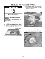
Remove the top cover from the washer. Replace all parts and panels before servicing. Pressure Switch Pressure Hose 6. Electrical Shock Hazard Disconnect power before operating. Unplug washer or disconnect power. 2. Turn 90° CW To Remove 4-7 Pull the pressure hose off the water supply to do so can result in the chassis, ...
Remove the top cover from the washer. Replace all parts and panels before servicing. Pressure Switch Pressure Hose 6. Electrical Shock Hazard Disconnect power before operating. Unplug washer or disconnect power. 2. Turn 90° CW To Remove 4-7 Pull the pressure hose off the water supply to do so can result in the chassis, ...
User Guide
Page 46
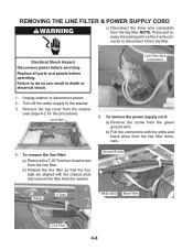
... page 4-2 for the procedure). To remove the power supply cord: a) Remove the screw from the filter. Failure to the washer. 3. NOTE: Press and release the locking arm on the 2-wire connector to disconnect it from the green ground wire. Line Filter 5. b) ...Pull the connectors with the chassis slots and remove the filter from the washer. Replace all parts and panels before servicing. REMOVING THE LINE FILTER & POWER SUPPLY CORD c) Disconnect the three wire connectors from the line filter terminals. 4. b)...
... page 4-2 for the procedure). To remove the power supply cord: a) Remove the screw from the filter. Failure to the washer. 3. NOTE: Press and release the locking arm on the 2-wire connector to disconnect it from the green ground wire. Line Filter 5. b) ...Pull the connectors with the chassis slots and remove the filter from the washer. Replace all parts and panels before servicing. REMOVING THE LINE FILTER & POWER SUPPLY CORD c) Disconnect the three wire connectors from the line filter terminals. 4. b)...
User Guide
Page 48
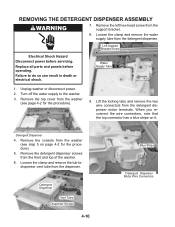
...parts and panels before servicing. Unplug washer or disconnect power. 2. Detergent Dispenser Vent Tube Dispenser Screws 4-10 Blue Stripe Detergent Dispenser Motor Wire Connectors Lift the locking tabs and remove the two wire connectors from the washer... before operating. Detergent Dispenser 4. Water Supply Tube 1. Failure to the washer. 3. Remove the left hex-head screw from the dispenser. Loosen the clamp and remove the water... supply tube from the washer (see step 5 on it. Turn off the water supply to do ...
...parts and panels before servicing. Unplug washer or disconnect power. 2. Detergent Dispenser Vent Tube Dispenser Screws 4-10 Blue Stripe Detergent Dispenser Motor Wire Connectors Lift the locking tabs and remove the two wire connectors from the washer... before operating. Detergent Dispenser 4. Water Supply Tube 1. Failure to the washer. 3. Remove the left hex-head screw from the dispenser. Loosen the clamp and remove the water... supply tube from the washer (see step 5 on it. Turn off the water supply to do ...
User Guide
Page 51
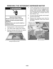
... Pry up on top. Turn off the water supply to do so can result in death or electrical shock. 5. Replace all parts and panels before servicing. Remove the top cover from the detergent dispenser motor and remove the motor. Electrical Shock Hazard Disconnect power ...before operating. Cam Actuator Blue Stripe Detergent Dispenser Motor Dispenser Motor Wire Connectors 4-13 Remove the mounting screw from the washer (see page 4-2 for the procedure). Mounting Screw Motor Shaft 1. Lift the locking tabs and remove the two wire connectors from the ...
... Pry up on top. Turn off the water supply to do so can result in death or electrical shock. 5. Replace all parts and panels before servicing. Remove the top cover from the detergent dispenser motor and remove the motor. Electrical Shock Hazard Disconnect power ...before operating. Cam Actuator Blue Stripe Detergent Dispenser Motor Dispenser Motor Wire Connectors 4-13 Remove the mounting screw from the washer (see page 4-2 for the procedure). Mounting Screw Motor Shaft 1. Lift the locking tabs and remove the two wire connectors from the ...
User Guide
Page 52
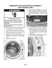
... assembly. Remove the lower front access panel (see page 4-2 for the procedure). 5. b) Remove the two T-20 Torx screws from around the front of the bellows, and remove the wire. Replace all parts and panels before servicing. Failure to the washer. 3. Retaining Wire Tension ...Spring 7. Electrical Shock Hazard Disconnect power before operating. Unplug washer or disconnect power. 2. Turn off the ...
... assembly. Remove the lower front access panel (see page 4-2 for the procedure). 5. b) Remove the two T-20 Torx screws from around the front of the bellows, and remove the wire. Replace all parts and panels before servicing. Failure to the washer. 3. Retaining Wire Tension ...Spring 7. Electrical Shock Hazard Disconnect power before operating. Unplug washer or disconnect power. 2. Turn off the ...
User Guide
Page 55
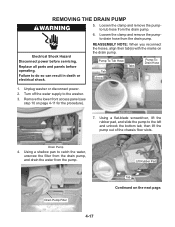
...from the drain pump. 6. Electrical Shock Hazard Disconnect power before operating. Pump-To-Tub Hose Tab Arrow Tabs Pump-ToDrain Hose 1. Unplug washer or disconnect power. 2. Remove the lower front access panel (see step 10 on the next page. Using a flat-blade screwdriver, lift the rubber pad, and slide the pump to...the drain pump, and drain the water from the pump. Loosen the clamp and remove the pumpto-tub hose from the drain pump. Replace all parts and panels before servicing. Using a shallow pan to the left and unhook the bottom tab, then lift the pump out of the chassis floor ...
...from the drain pump. 6. Electrical Shock Hazard Disconnect power before operating. Pump-To-Tub Hose Tab Arrow Tabs Pump-ToDrain Hose 1. Unplug washer or disconnect power. 2. Remove the lower front access panel (see step 10 on the next page. Using a flat-blade screwdriver, lift the rubber pad, and slide the pump to...the drain pump, and drain the water from the pump. Loosen the clamp and remove the pumpto-tub hose from the drain pump. Replace all parts and panels before servicing. Using a shallow pan to the left and unhook the bottom tab, then lift the pump out of the chassis floor ...
User Guide
Page 57
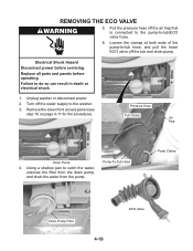
Remove the lower front access panel (see step 10 on page 4-11 for the procedure). Pressure Hose Tub Clamp Air Trap Drain Pump 4. Pump-To-Tub Hose Pump Clamp Drain Pump Filter 4-19 ECO Valve Loosen the clamps at both ends of the pump-to the washer. 3. Unplug washer or disconnect power. 2. Turn off... Disconnect power before operating. Using a shallow pan to -tub/ECO valve hose. 6. Failure to do so can result in death or electrical shock. 1. Replace all parts and panels before servicing. REMOVING THE ECO VALVE 5.
Remove the lower front access panel (see step 10 on page 4-11 for the procedure). Pressure Hose Tub Clamp Air Trap Drain Pump 4. Pump-To-Tub Hose Pump Clamp Drain Pump Filter 4-19 ECO Valve Loosen the clamps at both ends of the pump-to the washer. 3. Unplug washer or disconnect power. 2. Turn off... Disconnect power before operating. Using a shallow pan to -tub/ECO valve hose. 6. Failure to do so can result in death or electrical shock. 1. Replace all parts and panels before servicing. REMOVING THE ECO VALVE 5.


