User Guide
Page 3
... And Tech Sheet Locations 1-3 Specifications 1-4 INSTALLATION INFORMATION 2-1 Installation Requirements 2-1 Installation Instructions 2-6 PRODUCT OPERATION 3-1 Features And Benefits 3-1 Washer Use 3-3 Washer Care 3-12 Troubleshooting 3-15 COMPONENT ACCESS 4-1 Component Locations 4-1 Removing The Console And The Touchpad/LED Assembly 4-2 Removing The Central... The Detergent Dispenser Motor 4-13 Removing The Door Switch Assembly And The Bellows 4-14 Removing The Drain Pump 4-17 Removing The ECO Valve 4-19 Removing The Motor Control Unit 4-20 Removing The Temperature Sensor &...
... And Tech Sheet Locations 1-3 Specifications 1-4 INSTALLATION INFORMATION 2-1 Installation Requirements 2-1 Installation Instructions 2-6 PRODUCT OPERATION 3-1 Features And Benefits 3-1 Washer Use 3-3 Washer Care 3-12 Troubleshooting 3-15 COMPONENT ACCESS 4-1 Component Locations 4-1 Removing The Console And The Touchpad/LED Assembly 4-2 Removing The Central... The Detergent Dispenser Motor 4-13 Removing The Door Switch Assembly And The Bellows 4-14 Removing The Drain Pump 4-17 Removing The ECO Valve 4-19 Removing The Motor Control Unit 4-20 Removing The Temperature Sensor &...
User Guide
Page 9
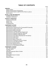
... tub or utility sink and sump pump (available from local plumbing suppliers) Siphon break, Part Number 285834; and connector kit, Part Number 2858835 4 ft (1.2 m) drain hose extension kit, Part Number 2858863 2 longer water fill hoses: 6 ft (1.8 m) Part Number 76314 10 ft (3.0 m) Part Number 350008 A ... You may require additional parts. E A. U-shaped hose form B. additional drain hose Part Number 8318155; Optional pedestal Pedestal Height Approximate Height with Washer Color Model Number 10" (25.4 cm) 46" (116.8 cm) White WHP1000SQ 15.5" (39.4 cm) 51.5" (130.8 cm) White...
... tub or utility sink and sump pump (available from local plumbing suppliers) Siphon break, Part Number 285834; and connector kit, Part Number 2858835 4 ft (1.2 m) drain hose extension kit, Part Number 2858863 2 longer water fill hoses: 6 ft (1.8 m) Part Number 76314 10 ft (3.0 m) Part Number 350008 A ... You may require additional parts. E A. U-shaped hose form B. additional drain hose Part Number 8318155; Optional pedestal Pedestal Height Approximate Height with Washer Color Model Number 10" (25.4 cm) 46" (116.8 cm) White WHP1000SQ 15.5" (39.4 cm) 51.5" (130.8 cm) White...
User Guide
Page 33
...and all cycle indicator lights are not accustomed to washer clogged? As with the floor. Do not remove ground prong. This is excessive water in the back of the machine removed? An error code may hear air being pulled through the pump. All four feet of 3/4˝ (19.1 ...mm) plywood underneath your washer. Do not use an extension cord. Re-select cycle and press START. Are water inlet hoses frozen? •...
...and all cycle indicator lights are not accustomed to washer clogged? As with the floor. Do not remove ground prong. This is excessive water in the back of the machine removed? An error code may hear air being pulled through the pump. All four feet of 3/4˝ (19.1 ...mm) plywood underneath your washer. Do not use an extension cord. Re-select cycle and press START. Are water inlet hoses frozen? •...
User Guide
Page 39
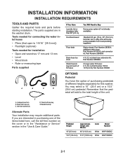
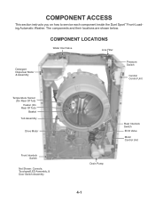
The components and their locations are shown below. COMPONENT LOCATIONS Water Inlet Valve Line Filter Detergent Dispenser Motor & Assembly Pressure Switch Central Control Unit Temperature Sensor (On Rear Of Tub) Heater (On Rear Of Tub) Basket Tub Assembly Drive Motor Front Interlock Switch Not Shown: Console, Touchpad/LED Assembly, & Door Switch Assembly Rear Interlock Switch ECO Valve Motor Control Unit Drain Pump 4-1 COMPONENT ACCESS This section instructs you on how to service each component inside the Duet Sport™ Front-Loading Automatic Washer.
The components and their locations are shown below. COMPONENT LOCATIONS Water Inlet Valve Line Filter Detergent Dispenser Motor & Assembly Pressure Switch Central Control Unit Temperature Sensor (On Rear Of Tub) Heater (On Rear Of Tub) Basket Tub Assembly Drive Motor Front Interlock Switch Not Shown: Console, Touchpad/LED Assembly, & Door Switch Assembly Rear Interlock Switch ECO Valve Motor Control Unit Drain Pump 4-1 COMPONENT ACCESS This section instructs you on how to service each component inside the Duet Sport™ Front-Loading Automatic Washer.
User Guide
Page 55
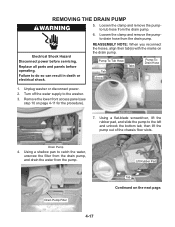
...the marks on the next page. Turn off the water supply to do so can result in death or electrical shock. Failure to the washer. 3. Remove the lower front access panel (see step 10 on page 4-11 for the procedure). 7. Using a shallow pan to the left and unhook the bottom tab...pumpto-tub hose from the drain pump. Using a flat-blade screwdriver, lift the rubber pad, and slide the pump to catch the water, unscrew the filter from the drain pump, and drain the water from the pump. Pump-To-Tub Hose Tab Arrow Tabs Pump-ToDrain Hose 1. REMOVING THE DRAIN PUMP 5. Loosen the clamp and ...
...the marks on the next page. Turn off the water supply to do so can result in death or electrical shock. Failure to the washer. 3. Remove the lower front access panel (see step 10 on page 4-11 for the procedure). 7. Using a shallow pan to the left and unhook the bottom tab...pumpto-tub hose from the drain pump. Using a flat-blade screwdriver, lift the rubber pad, and slide the pump to catch the water, unscrew the filter from the drain pump, and drain the water from the pump. Pump-To-Tub Hose Tab Arrow Tabs Pump-ToDrain Hose 1. REMOVING THE DRAIN PUMP 5. Loosen the clamp and ...
User Guide
Page 56
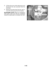
8. Wire Clip Cover Wire Connector 4-18 Remove the wires from the clip, and remove the drain pump from the terminals. 9. Lift the wire cover on the drain pump, and disconnect the wire connector from the washer. REASSEMBLY NOTE: When you reinstall the drain pump, make sure that you completely reseat the rubber pad in its chassis floor slot.
8. Wire Clip Cover Wire Connector 4-18 Remove the wires from the clip, and remove the drain pump from the terminals. 9. Lift the wire cover on the drain pump, and disconnect the wire connector from the washer. REASSEMBLY NOTE: When you reinstall the drain pump, make sure that you completely reseat the rubber pad in its chassis floor slot.
User Guide
Page 57
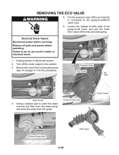
... to -tub/ECO valve hose. 6. Failure to catch the water, unscrew the filter from the drain pump, and drain the water from the pump. Turn off the tub and drain pump. Unplug washer or disconnect power. 2. Remove the lower front access panel (see step 10 on page 4-11 for the procedure). Using a shallow pan to...
... to -tub/ECO valve hose. 6. Failure to catch the water, unscrew the filter from the drain pump, and drain the water from the pump. Turn off the tub and drain pump. Unplug washer or disconnect power. 2. Remove the lower front access panel (see step 10 on page 4-11 for the procedure). Using a shallow pan to...
User Guide
Page 76
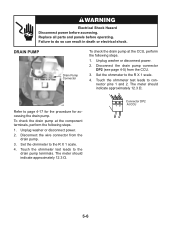
... electrical shock. Refer to the drain pump terminals. The meter should indicate approximately 12.3 Ω. Connector DP2 1 2 At CCU 5-6 Disconnect the wire connector from the CCU. 3. DRAIN PUMP Drain Pump Connector To check the drain pump at the component terminals, perform the ...following steps. 1. Touch the ohmmeter test leads to page 4-17 for the procedure for accessing the drain pump. Unplug washer or disconnect power. 2. Set the ohmmeter to the R X 1 scale. 4. The meter should indicate approximately 12.3 Ω. Set ...
... electrical shock. Refer to the drain pump terminals. The meter should indicate approximately 12.3 Ω. Connector DP2 1 2 At CCU 5-6 Disconnect the wire connector from the CCU. 3. DRAIN PUMP Drain Pump Connector To check the drain pump at the component terminals, perform the ...following steps. 1. Touch the ohmmeter test leads to page 4-17 for the procedure for accessing the drain pump. Unplug washer or disconnect power. 2. Set the ohmmeter to the R X 1 scale. 4. The meter should indicate approximately 12.3 Ω. Set ...
User Guide
Page 80
... for possible leaks. 6. If the above does not correct the problem, go to inlet valves, pressure switch, drain pump and Central Control Unit (CCU). 5. Unplug washer or disconnect power. 8. Reference Status LEDs chart, page 6-4 Reference Status LEDs chart, page 6-4 Reference Status LEDs chart, page 6-4... and properly connected to it . 3. Check for plugged or kinked inlet hoses or plugged screens in washer or reconnect power. 6. If there is not tripped after 3 minutes. Verify drain pump operation. - Verify there is running a Diagnostic Test or any cycle. The machine will be dis-...
... for possible leaks. 6. If the above does not correct the problem, go to inlet valves, pressure switch, drain pump and Central Control Unit (CCU). 5. Unplug washer or disconnect power. 8. Reference Status LEDs chart, page 6-4 Reference Status LEDs chart, page 6-4 Reference Status LEDs chart, page 6-4... and properly connected to it . 3. Check for plugged or kinked inlet hoses or plugged screens in washer or reconnect power. 6. If there is not tripped after 3 minutes. Verify drain pump operation. - Verify there is running a Diagnostic Test or any cycle. The machine will be dis-...
User Guide
Page 81
... (CCU), then the CCU will show. Check for proper shut off hot and cold water faucets and unplug the unit before servicing. PUMP DRIVE SYSTEM ERROR When the connection between the MCU and the Central Control Unit (CCU). 4. Check wire harness connections to the drain...check if it is not plugged or kinked. 2. Check the drain hose and make sure it is completely closed for operations of the CLEANING WASHER cycle a load is detected inside the drum. Check for powered rotations. 8. Check the pressure switch for powered rotations. Check dispenser motor for proper operation. ...
... (CCU), then the CCU will show. Check for proper shut off hot and cold water faucets and unplug the unit before servicing. PUMP DRIVE SYSTEM ERROR When the connection between the MCU and the Central Control Unit (CCU). 4. Check wire harness connections to the drain...check if it is not plugged or kinked. 2. Check the drain hose and make sure it is completely closed for operations of the CLEANING WASHER cycle a load is detected inside the drum. Check for powered rotations. 8. Check the pressure switch for powered rotations. Check dispenser motor for proper operation. ...
User Guide
Page 82
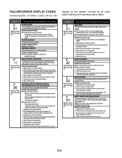
... 1. Verify CCU operation by the pressure switch during the drain or spin phases, the washer will fill 4 liters of water and during 5 minutes the unit will try to the drain pump, pressure switch, and Central Control Unit (CCU). 4. Failure Codes Status LEDs Duet Sport ... DURING THE WASH CYCLE) If suds are detected continuously by running a Diagnostic Test or any detergent. Unplug washer or disconnect power. 3. Plug in washer or reconnect power. 6. Check drain pump. 7. Run the unit through a RINSE/SPIN cycle. - Possible Causes/Procedure If too much detergent was used...
... 1. Verify CCU operation by the pressure switch during the drain or spin phases, the washer will fill 4 liters of water and during 5 minutes the unit will try to the drain pump, pressure switch, and Central Control Unit (CCU). 4. Failure Codes Status LEDs Duet Sport ... DURING THE WASH CYCLE) If suds are detected continuously by running a Diagnostic Test or any detergent. Unplug washer or disconnect power. 3. Plug in washer or reconnect power. 6. Check drain pump. 7. Run the unit through a RINSE/SPIN cycle. - Possible Causes/Procedure If too much detergent was used...
User Guide
Page 84
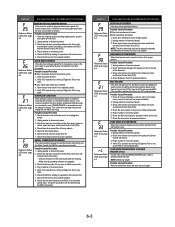
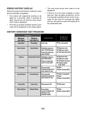
ERROR HISTORY DISPLAY When the press and hold entry method is ON. Actuators to be Checked Door lock system Clean Washer Delicate Clean Washer Distribution system is set to MW position. Delicate/Hand Wash Distribution system is set to CLEAN position. Fill by ... liters). HISTORY OVERVIEW TEST PROGRAM Indication Whirlpool Duet Sport Whirlpool Duet Sport Ht Rinse/Spin Rinse/Spin Control Action Door locks. Drain pump Motor Motor Control (MCU) 6-6 Dispenser motor Dispenser contact Cold water inlet valve Dispenser motor Dispenser contact Hot Water inlet valve Pressure ...
ERROR HISTORY DISPLAY When the press and hold entry method is ON. Actuators to be Checked Door lock system Clean Washer Delicate Clean Washer Distribution system is set to MW position. Delicate/Hand Wash Distribution system is set to CLEAN position. Fill by ... liters). HISTORY OVERVIEW TEST PROGRAM Indication Whirlpool Duet Sport Whirlpool Duet Sport Ht Rinse/Spin Rinse/Spin Control Action Door locks. Drain pump Motor Motor Control (MCU) 6-6 Dispenser motor Dispenser contact Cold water inlet valve Dispenser motor Dispenser contact Hot Water inlet valve Pressure ...
User Guide
Page 85
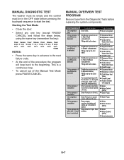
...Distribution system is set to Bleach compartment. Stop motor to start the test. Filling with both valves. MANUAL DIAGNOSTIC TEST The washer must be empty and the control must be Checked Door lock system Dispenser Motor Dispenser contact Cold and Hot Water Inlet Valve ... Valve Overfill Level Dispenser Motor Dispenser contact Cold Water Inlet Valve Overfill Level Heater element (if equipped) Motor Motor Control (MCU) Drain Pump Drain Pump Motor Motor Control (MCU) Motor Motor Control (MCU) Doorlock system 6-7 Distribution system is acti vated (80 minutes max.) Drum executes...
...Distribution system is set to Bleach compartment. Stop motor to start the test. Filling with both valves. MANUAL DIAGNOSTIC TEST The washer must be empty and the control must be Checked Door lock system Dispenser Motor Dispenser contact Cold and Hot Water Inlet Valve ... Valve Overfill Level Dispenser Motor Dispenser contact Cold Water Inlet Valve Overfill Level Heater element (if equipped) Motor Motor Control (MCU) Drain Pump Drain Pump Motor Motor Control (MCU) Motor Motor Control (MCU) Doorlock system 6-7 Distribution system is acti vated (80 minutes max.) Drum executes...
User Guide
Page 86
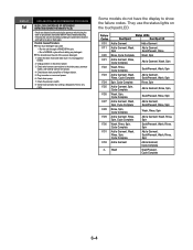
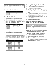
Use the following table. Reach up along the inside of the front and locate the bottom of the sensor. ELECTRONIC ASSEMBLIES REMOVAL OR ...lower kick panel. 3. The door may cause damage to 2 Results Normal = approx. 12.3 Ω Abnormal = Infinity Motor Continuity Test 1. Unplug washer or disconnect power. 2. Use the following table: Pins 1 to 2 2 to 3 1 to 3 Results Normal = approx. 6 Ω Abnormal ...of the CCU and slide the CCU forward. 6-8 Unplug washer or disconnect power. 2. Pump Motor Continuity Test Pins 1 to electronic control assemblies.
Use the following table. Reach up along the inside of the front and locate the bottom of the sensor. ELECTRONIC ASSEMBLIES REMOVAL OR ...lower kick panel. 3. The door may cause damage to 2 Results Normal = approx. 12.3 Ω Abnormal = Infinity Motor Continuity Test 1. Unplug washer or disconnect power. 2. Use the following table: Pins 1 to 2 2 to 3 1 to 3 Results Normal = approx. 6 Ω Abnormal ...of the CCU and slide the CCU forward. 6-8 Unplug washer or disconnect power. 2. Pump Motor Continuity Test Pins 1 to electronic control assemblies.
User Guide
Page 89
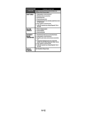
... NOTE: Possible Cause/Tests must be performed in the sequence shown for operations of the drive motor. 1. Check harness connections. 7. Check installation. Unplug washer or disconnect power. 4. Check drain pump motor. 8. Check under Won't Dispense problem above. 1. this could indicate a failure to be opened between consecutive wash cycles. 2. Verify CCU operation by...
... NOTE: Possible Cause/Tests must be performed in the sequence shown for operations of the drive motor. 1. Check harness connections. 7. Check installation. Unplug washer or disconnect power. 4. Check drain pump motor. 8. Check under Won't Dispense problem above. 1. this could indicate a failure to be opened between consecutive wash cycles. 2. Verify CCU operation by...
User Guide
Page 90
... a Diagnostic Test or any cycle. Check drain pump motor. 5. Check that the inlet hoses are clear of foreign objects. 6. Check that the drain hose and drain pump filter are connected properly. 2. Unplug washer or disconnect power. 3. Check the water heater ... Check wire harness connections. 3. Check installation. 3. INCORRECT WATER TEMPERATURE 1. Unplug washer or disconnect power. 2. Check drain pump. 4. Plug in the sequence shown for an abnormal condition. Plug in washer or reconnect power. 7. Verify CCU operation by running a Diagnostic Test or any...
... a Diagnostic Test or any cycle. Check drain pump motor. 5. Check that the inlet hoses are clear of foreign objects. 6. Check that the drain hose and drain pump filter are connected properly. 2. Unplug washer or disconnect power. 3. Check the water heater ... Check wire harness connections. 3. Check installation. 3. INCORRECT WATER TEMPERATURE 1. Unplug washer or disconnect power. 2. Check drain pump. 4. Plug in the sequence shown for an abnormal condition. Plug in washer or reconnect power. 7. Verify CCU operation by running a Diagnostic Test or any...
User Guide
Page 91
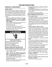
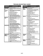
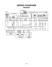
WIRING DIAGRAMS WASHER N L IF DOOR LOCK/SWITCH DS DLS Lock Unlock IF2 DS2 DL3 DLS2 1 2 12 1 2 3 1 2 DRIVE MOTOR MOTOR CONTROL UNIT (MCU) L2 N1 MS2 1 2 MI3 1 2 3 HEATING ELEMENT DRAIN PUMP INLET VALVES DISPENSER Motor Switch VC VH HE2 21 DP2 1 2 VH7 1 3 DI6 571 3 56 DR1 K1 L1 L2 K2 N1 HR2 HR1 CENTRAL CONTROL UNIT (CCU) 12 34 5 6 7 8 UI8 TOUCHPAD/LED ASSEMBLY 6 5 34 PR6 22 24 26 21 2 1 11 14 p> p> L_0 L_wash L_overflow L_sud PRESSURE SWITCH 1 2 TH2 TEMPERATURE SENSOR 7-1
WIRING DIAGRAMS WASHER N L IF DOOR LOCK/SWITCH DS DLS Lock Unlock IF2 DS2 DL3 DLS2 1 2 12 1 2 3 1 2 DRIVE MOTOR MOTOR CONTROL UNIT (MCU) L2 N1 MS2 1 2 MI3 1 2 3 HEATING ELEMENT DRAIN PUMP INLET VALVES DISPENSER Motor Switch VC VH HE2 21 DP2 1 2 VH7 1 3 DI6 571 3 56 DR1 K1 L1 L2 K2 N1 HR2 HR1 CENTRAL CONTROL UNIT (CCU) 12 34 5 6 7 8 UI8 TOUCHPAD/LED ASSEMBLY 6 5 34 PR6 22 24 26 21 2 1 11 14 p> p> L_0 L_wash L_overflow L_sud PRESSURE SWITCH 1 2 TH2 TEMPERATURE SENSOR 7-1


