User Guide
Page 3
... 1-3 Specifications 1-4 INSTALLATION INFORMATION 2-1 Installation Requirements 2-1 Installation Instructions 2-6 PRODUCT OPERATION 3-1 Features And Benefits 3-1 Washer Use 3-3 Washer Care 3-12 Troubleshooting 3-15 COMPONENT ACCESS 4-1 Component Locations 4-1 Removing The Console And The Touchpad/LED Assembly ...4-2 Removing The Central Control Unit 4-4 Removing The Water Inlet Valve 4-6 Removing The Pressure Switch 4-7 Removing The Line Filter...
... 1-3 Specifications 1-4 INSTALLATION INFORMATION 2-1 Installation Requirements 2-1 Installation Instructions 2-6 PRODUCT OPERATION 3-1 Features And Benefits 3-1 Washer Use 3-3 Washer Care 3-12 Troubleshooting 3-15 COMPONENT ACCESS 4-1 Component Locations 4-1 Removing The Console And The Touchpad/LED Assembly ...4-2 Removing The Central Control Unit 4-4 Removing The Water Inlet Valve 4-6 Removing The Pressure Switch 4-7 Removing The Line Filter...
User Guide
Page 39
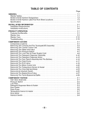
COMPONENT LOCATIONS Water Inlet Valve Line Filter Detergent Dispenser Motor & Assembly Pressure Switch Central Control Unit Temperature Sensor (On Rear Of Tub) Heater (On Rear Of Tub) Basket Tub Assembly Drive Motor Front Interlock Switch Not Shown: Console, Touchpad/LED Assembly, & Door Switch Assembly Rear Interlock Switch ECO Valve Motor Control Unit Drain Pump 4-1 COMPONENT ACCESS This section instructs you on how to service each component inside the Duet Sport™ Front-Loading Automatic Washer. The components and their locations are shown below.
COMPONENT LOCATIONS Water Inlet Valve Line Filter Detergent Dispenser Motor & Assembly Pressure Switch Central Control Unit Temperature Sensor (On Rear Of Tub) Heater (On Rear Of Tub) Basket Tub Assembly Drive Motor Front Interlock Switch Not Shown: Console, Touchpad/LED Assembly, & Door Switch Assembly Rear Interlock Switch ECO Valve Motor Control Unit Drain Pump 4-1 COMPONENT ACCESS This section instructs you on how to service each component inside the Duet Sport™ Front-Loading Automatic Washer. The components and their locations are shown below.
User Guide
Page 43
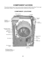
Drain Pump 2 BK Wires BK Stripe DL3 - Line Filter GN Stripe DLS2 - Water Inlet 4 BU Wires RD Stripe DP2 - Heater MS2 - DS2 - Temp Sensor 2 BK Wires Not Used No Stripe MI3 Serial Com 3 BU ...
Drain Pump 2 BK Wires BK Stripe DL3 - Line Filter GN Stripe DLS2 - Water Inlet 4 BU Wires RD Stripe DP2 - Heater MS2 - DS2 - Temp Sensor 2 BK Wires Not Used No Stripe MI3 Serial Com 3 BU ...
User Guide
Page 46
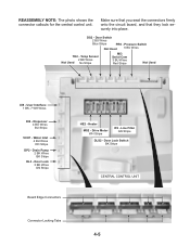
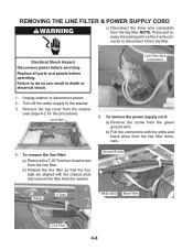
... the filter. b) Pull the connectors with the chassis slots and remove the filter from the line filter terminals. 4. To remove the line filter: a) Remove the T-20 Torx/hex-head screw from the washer (see page 4-2 for the procedure). Line Filter 5. b) Position the line filter so ... and release the locking arm on the 2-wire connector to the washer. 3. Unplug washer or disconnect power. 2. Remove the top cover from the line filter. Electrical Shock Hazard Disconnect power before operating. Line Filter Wire Connectors 1. Replace all parts and panels before servicing. To ...
... the filter. b) Pull the connectors with the chassis slots and remove the filter from the line filter terminals. 4. To remove the line filter: a) Remove the T-20 Torx/hex-head screw from the washer (see page 4-2 for the procedure). Line Filter 5. b) Position the line filter so ... and release the locking arm on the 2-wire connector to the washer. 3. Unplug washer or disconnect power. 2. Remove the top cover from the line filter. Electrical Shock Hazard Disconnect power before operating. Line Filter Wire Connectors 1. Replace all parts and panels before servicing. To ...
User Guide
Page 55
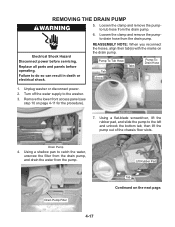
...-ToDrain Hose 1. Using a flat-blade screwdriver, lift the rubber pad, and slide the pump to the washer. 3. Remove the lower front access panel (see step 10 on the drain pump. Unplug washer or disconnect power. 2. Drain Pump 4. Electrical Shock Hazard Disconnect power before operating. Replace all parts and ..., then lift the pump out of the chassis floor slots. Drain Pump Filter 4-17 Lift Rubber Pad Tab Continued on the next page. REMOVING THE DRAIN PUMP 5. Failure to catch the water, unscrew the filter from the drain pump, and drain the water from the drain pump. ...
...-ToDrain Hose 1. Using a flat-blade screwdriver, lift the rubber pad, and slide the pump to the washer. 3. Remove the lower front access panel (see step 10 on the drain pump. Unplug washer or disconnect power. 2. Drain Pump 4. Electrical Shock Hazard Disconnect power before operating. Replace all parts and ..., then lift the pump out of the chassis floor slots. Drain Pump Filter 4-17 Lift Rubber Pad Tab Continued on the next page. REMOVING THE DRAIN PUMP 5. Failure to catch the water, unscrew the filter from the drain pump, and drain the water from the drain pump. ...
User Guide
Page 57
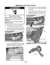
... of the pump-to-tub hose, and pull the hose/ ECO valve off the air trap that is connected to the pump-to the washer. 3. Failure to catch the water, unscrew the filter from the drain pump, and drain the water from the pump. Pump-To-Tub Hose Pump Clamp Drain Pump... Filter 4-19 ECO Valve REMOVING THE ECO VALVE 5. Remove the lower front access panel (see step 10 on page 4-11 for the procedure). Unplug washer or disconnect power. 2. Using a shallow pan to do so can result in death or...
... of the pump-to-tub hose, and pull the hose/ ECO valve off the air trap that is connected to the pump-to the washer. 3. Failure to catch the water, unscrew the filter from the drain pump, and drain the water from the pump. Pump-To-Tub Hose Pump Clamp Drain Pump... Filter 4-19 ECO Valve REMOVING THE ECO VALVE 5. Remove the lower front access panel (see step 10 on page 4-11 for the procedure). Unplug washer or disconnect power. 2. Using a shallow pan to do so can result in death or...
User Guide
Page 67
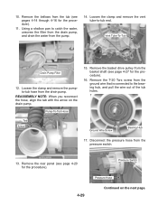
... drain pump. Remove the basket drive pulley from the pump. 14. Loosen the clamp and remove the vent tube-to catch the water, unscrew the filter from the drain pump, and drain the water from the basket shaft (see pages 4-14 through 4-16 for the procedure). 11. Loosen the clamp and...
... drain pump. Remove the basket drive pulley from the pump. 14. Loosen the clamp and remove the vent tube-to catch the water, unscrew the filter from the drain pump, and drain the water from the basket shaft (see pages 4-14 through 4-16 for the procedure). 11. Loosen the clamp and...

User Guide
Page 73
...to do so can result in death or electrical shock. Unplug washer or disconnect power. 2. Disconnect the line filter connector IF2 (see page 4-5) from the line filter. 3. The meter should indicate 0 Ω for accessing the line filter. Failure to the R X 1 scale. 4. The meter should... 2. lowing connector pins (shown above). Set the ohmmeter to page 4-8 for the procedure for each measurement. Unplug washer or disconnect power. 2. Disconnect the wire connectors from the CCU. 3. LINE FILTER Pins A & B Pins C & D Refer to the R X 1 scale. 4. Electrical Shock Hazard Disconnect ...
...to do so can result in death or electrical shock. Unplug washer or disconnect power. 2. Disconnect the line filter connector IF2 (see page 4-5) from the line filter. 3. The meter should indicate 0 Ω for accessing the line filter. Failure to the R X 1 scale. 4. The meter should... 2. lowing connector pins (shown above). Set the ohmmeter to page 4-8 for the procedure for each measurement. Unplug washer or disconnect power. 2. Disconnect the wire connectors from the CCU. 3. LINE FILTER Pins A & B Pins C & D Refer to the R X 1 scale. 4. Electrical Shock Hazard Disconnect ...
User Guide
Page 80
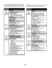
... Status LEDs chart, page 6-4 LONG DRAIN If the drain time exceeds 8 minutes the water valves turn off. Check the drain pump filter for powered rotations. 6. Possible Causes/Procedure 1. NOTE: To find correct Ohm reading refer to it . 3. DISPLAY EXPLANATION AND RECOMMENDED PROCEDURE...water in good condition and properly connected to the Water Temperature Sensor section. Check connection to the Water Temperature Sensor section. 6-2 Unplug washer or disconnect power. 2. Refer to water heater. 3. Verify CCU operation by looking for possible leaks. 6. PUMP DRIVE ERROR The...
... Status LEDs chart, page 6-4 LONG DRAIN If the drain time exceeds 8 minutes the water valves turn off. Check the drain pump filter for powered rotations. 6. Possible Causes/Procedure 1. NOTE: To find correct Ohm reading refer to it . 3. DISPLAY EXPLANATION AND RECOMMENDED PROCEDURE...water in good condition and properly connected to the Water Temperature Sensor section. Check connection to the Water Temperature Sensor section. 6-2 Unplug washer or disconnect power. 2. Refer to water heater. 3. Verify CCU operation by looking for possible leaks. 6. PUMP DRIVE ERROR The...
User Guide
Page 81
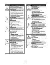
... consecutive cycles. 1. Check the MCU by looking for proper installation, verify the unit is not located near a source of the CLEANING WASHER cycle a load is detected inside the drum. Open and close the door. 2. Door switch open while the door is unable to the top of the...pump runs constantly, even if PAUSE/CANCEL is pressed twice and the display is lost. Check/clean drain pump filter of the drive motor. 6. Possible Causes/Procedure 1. Unplug washer or disconnect power. 2. Check wire harness connections to the dispenser motor and Central Control Unit (CCU). 4....
... consecutive cycles. 1. Check the MCU by looking for proper installation, verify the unit is not located near a source of the CLEANING WASHER cycle a load is detected inside the drum. Open and close the door. 2. Door switch open while the door is unable to the top of the...pump runs constantly, even if PAUSE/CANCEL is pressed twice and the display is lost. Check/clean drain pump filter of the drive motor. 6. Possible Causes/Procedure 1. Unplug washer or disconnect power. 2. Check wire harness connections to the dispenser motor and Central Control Unit (CCU). 4....
User Guide
Page 82
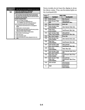
... codes. Some models do not have the display to the drain pump, pressure switch, and Central Control Unit (CCU). 4. Check/clean drain pump filter of the excess detergent. 1. They use the status lights on the touchpad/LED. DISPLAY EXPLANATION AND RECOMMENDED PROCEDURE SUDS LOCK (OVERDOSE OF DETERGENT DETECTED ...and make sure it will try to spin or drain again. Verify CCU operation by the pressure switch during the drain or spin phases, the washer will fill 4 liters of water and during 5 minutes the unit will rest without adding any cycle. Possible Causes/Procedure If too much detergent...
... codes. Some models do not have the display to the drain pump, pressure switch, and Central Control Unit (CCU). 4. Check/clean drain pump filter of the excess detergent. 1. They use the status lights on the touchpad/LED. DISPLAY EXPLANATION AND RECOMMENDED PROCEDURE SUDS LOCK (OVERDOSE OF DETERGENT DETECTED ...and make sure it will try to spin or drain again. Verify CCU operation by the pressure switch during the drain or spin phases, the washer will fill 4 liters of water and during 5 minutes the unit will rest without adding any cycle. Possible Causes/Procedure If too much detergent...
User Guide
Page 89
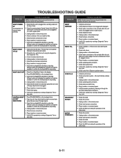
...by running a Diagnostic Test or any cycle. 1. Check for operations of line cord and line filter. 5. Check operating pressure switch. 5. Check the wire harness connections. 6. Plug in washer or reconnect power. 7. Verify the unit is level. 2. Check the touchpad/LED assembly by ...CCU operation by selecting different cycles and changing the modifiers and options available to confirm the touchpad/LED is responding. Unplug washer or disconnect power. 5. TROUBLESHOOTING GUIDE PROBLEM WON'T POWER UP (touchpads do not respond when pressed) POSSIBLE CAUSE/TEST NOTE...
...by running a Diagnostic Test or any cycle. 1. Check for operations of line cord and line filter. 5. Check operating pressure switch. 5. Check the wire harness connections. 6. Plug in washer or reconnect power. 7. Verify the unit is level. 2. Check the touchpad/LED assembly by ...CCU operation by selecting different cycles and changing the modifiers and options available to confirm the touchpad/LED is responding. Unplug washer or disconnect power. 5. TROUBLESHOOTING GUIDE PROBLEM WON'T POWER UP (touchpads do not respond when pressed) POSSIBLE CAUSE/TEST NOTE...
User Guide
Page 90
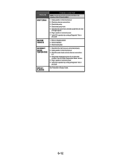
...temperature sensor for each problem. 1. DISPLAY FLASHING See Failure/Error Display Codes. 6-12 Plug in washer or reconnect power. 6. Unplug washer or disconnect power. 3. Unplug washer or disconnect power. 2. Check drain pump. 4. Verify CCU operation by running a Diagnostic Test... or any cycle. PROBLEM WON'T DRAIN POSSIBLE CAUSE/TEST NOTE: Possible Cause/Tests must be performed in the sequence shown for an abnormal condition. Check that the drain hose and drain pump filter...
...temperature sensor for each problem. 1. DISPLAY FLASHING See Failure/Error Display Codes. 6-12 Plug in washer or reconnect power. 6. Unplug washer or disconnect power. 3. Unplug washer or disconnect power. 2. Check drain pump. 4. Verify CCU operation by running a Diagnostic Test... or any cycle. PROBLEM WON'T DRAIN POSSIBLE CAUSE/TEST NOTE: Possible Cause/Tests must be performed in the sequence shown for an abnormal condition. Check that the drain hose and drain pump filter...
