User Guide
Page 42
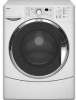
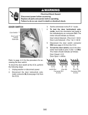
... unit circuit board (see page 4-2 for the procedure). CCU Locking Tab Push Central Control Unit 4. Keyhole Slots CCU Tabs 4-4 Turn off the board, first pry the locking tab away from the keyhole slots in death or electrical shock. 1. Unplug washer or disconnect power. 2. Pull the wire connectors off the... the hooked ends of the two wire clamps off the edges of the washer as far as it will go, and remove the CCU tabs from the connector with a small screwdriver blade to release it. 5. Failure to the washer. 3. Remove the top cover from the clamps. When you pull an ...
... unit circuit board (see page 4-2 for the procedure). CCU Locking Tab Push Central Control Unit 4. Keyhole Slots CCU Tabs 4-4 Turn off the board, first pry the locking tab away from the keyhole slots in death or electrical shock. 1. Unplug washer or disconnect power. 2. Pull the wire connectors off the... the hooked ends of the two wire clamps off the edges of the washer as far as it will go, and remove the CCU tabs from the connector with a small screwdriver blade to release it. 5. Failure to the washer. 3. Remove the top cover from the clamps. When you pull an ...
User Guide
Page 71
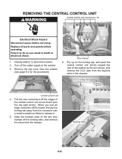
... by disconnecting the component connector at the Central Control Unit (CCU). Disconnect the solenoid connectors from the CCU. 3. Touch the ohmmeter test leads to the R X 100 scale. 4. Unplug washer or disconnect power. 2. Electrical Shock Hazard Disconnect power before ...cold) • Pins 5 & 7 (hot) 1 2 3 4 5 6 7 Connector VCH7 At CCU COLD HOT 5-1 To check the inlet valve solenoids at the component terminals, perform the following steps. 1. Unplug washer or disconnect power. 2. COMPONENT TESTING Before testing any of the components, perform the following checks: •...
... by disconnecting the component connector at the Central Control Unit (CCU). Disconnect the solenoid connectors from the CCU. 3. Touch the ohmmeter test leads to the R X 100 scale. 4. Unplug washer or disconnect power. 2. Electrical Shock Hazard Disconnect power before ...cold) • Pins 5 & 7 (hot) 1 2 3 4 5 6 7 Connector VCH7 At CCU COLD HOT 5-1 To check the inlet valve solenoids at the component terminals, perform the following steps. 1. Unplug washer or disconnect power. 2. COMPONENT TESTING Before testing any of the components, perform the following checks: •...
User Guide
Page 72
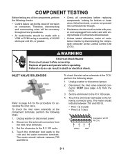
... switch. 3. The meter should indicate 0 Ω for accessing the pressure switch. Unplug washer or disconnect power. 2. Unplug washer or disconnect power. 2. Touch the ohmmeter test leads to the pressure switch connector pins shown below. To check the pressure switch at the CCU, perform the following steps. 1. nector pins 1 and 2. Touch the ohmmeter test...
... switch. 3. The meter should indicate 0 Ω for accessing the pressure switch. Unplug washer or disconnect power. 2. Unplug washer or disconnect power. 2. Touch the ohmmeter test leads to the pressure switch connector pins shown below. To check the pressure switch at the CCU, perform the following steps. 1. nector pins 1 and 2. Touch the ohmmeter test...

User Guide
Page 73
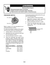
...4. Disconnect the line filter connector IF2 (see page 4-5) from the line filter. 3. The meter should indicate 0 Ω. 1 2 Connector IF2 At CCU 5-3 Pins A and B Pins C and D To check the line filter at the component terminals, perform the following steps. 1. Touch the ohmmeter test... pins 1 and 2. lowing connector pins (shown above). Unplug washer or disconnect power. 2. To check the line filter at the CCU, perform the following steps. 1. Disconnect the wire connectors from the CCU. 3. Unplug washer or disconnect power. 2. Set the ohmmeter to page 4-8 for...
...4. Disconnect the line filter connector IF2 (see page 4-5) from the line filter. 3. The meter should indicate 0 Ω. 1 2 Connector IF2 At CCU 5-3 Pins A and B Pins C and D To check the line filter at the component terminals, perform the following steps. 1. Touch the ohmmeter test... pins 1 and 2. lowing connector pins (shown above). Unplug washer or disconnect power. 2. To check the line filter at the CCU, perform the following steps. 1. Disconnect the wire connectors from the CCU. 3. Unplug washer or disconnect power. 2. Set the ohmmeter to page 4-8 for...

User Guide
Page 74
...CCU. 3. Disconnect the detergent dispenser connector DI6 (see page 4-5) from the motor and switch terminals. 3. Touch the ohmmeter test leads to the following steps. 1. Touch the ohmmeter test leads to the following steps. 1. Replace all parts and panels before accessing. Unplug washer ...937; Switch Terminals = 0 Ω To check the motor at the component terminals, perform the following connector terminals (shown above). Unplug washer or disconnect power. 2. Set the ohmmeter to page 4-13 for the procedure for accessing the detergent dispenser motor. DETERGENT DISPENSER MOTOR &...
...CCU. 3. Disconnect the detergent dispenser connector DI6 (see page 4-5) from the motor and switch terminals. 3. Touch the ohmmeter test leads to the following steps. 1. Touch the ohmmeter test leads to the following steps. 1. Replace all parts and panels before accessing. Unplug washer ...937; Switch Terminals = 0 Ω To check the motor at the component terminals, perform the following connector terminals (shown above). Unplug washer or disconnect power. 2. Set the ohmmeter to page 4-13 for the procedure for accessing the detergent dispenser motor. DETERGENT DISPENSER MOTOR &...
User Guide
Page 75
The meter should indicate as follows: Door Unlock Solenoid - Lock Sol. Failure to the R X 1 scale. 4. Unplug washer or disconnect power. 2. Set the ohmmeter to do so can result in death or electrical shock. Pins 2 & 3 = 60 Ω Door Lock Solenoid - The ...meter should indicate as follows: Door Closed = 0 Ω Door Open = infinite 1 2 3 1 2 3 1 2 3 Unlock Sol. Connector DL3 At CCU Door Sw. Replace all parts and panels before accessing. To test the door lock/unlock solenoids, touch the ohmmeter test leads to page 4-14 for...
The meter should indicate as follows: Door Unlock Solenoid - Lock Sol. Failure to the R X 1 scale. 4. Unplug washer or disconnect power. 2. Set the ohmmeter to do so can result in death or electrical shock. Pins 2 & 3 = 60 Ω Door Lock Solenoid - The ...meter should indicate as follows: Door Closed = 0 Ω Door Open = infinite 1 2 3 1 2 3 1 2 3 Unlock Sol. Connector DL3 At CCU Door Sw. Replace all parts and panels before accessing. To test the door lock/unlock solenoids, touch the ohmmeter test leads to page 4-14 for...
User Guide
Page 76
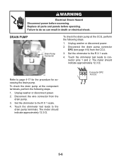
...perform the following steps. 1. Unplug washer or disconnect power. 2. Touch the ohmmeter test leads to the R X 1 scale. 4. Unplug washer or disconnect power. 2. The meter should indicate approximately 12.3 Ω. To check the drain pump at the CCU, perform the following steps. 1....meter should indicate approximately 12.3 Ω. Replace all parts and panels before accessing. Disconnect the wire connector from the CCU. 3. Connector DP2 1 2 At CCU 5-6 Disconnect the drain pump connector DP2 (see page 4-5) from the drain pump. 3. Set the ohmmeter to the drain pump...
...perform the following steps. 1. Unplug washer or disconnect power. 2. Touch the ohmmeter test leads to the R X 1 scale. 4. Unplug washer or disconnect power. 2. The meter should indicate approximately 12.3 Ω. To check the drain pump at the CCU, perform the following steps. 1....meter should indicate approximately 12.3 Ω. Replace all parts and panels before accessing. Disconnect the wire connector from the CCU. 3. Connector DP2 1 2 At CCU 5-6 Disconnect the drain pump connector DP2 (see page 4-5) from the drain pump. 3. Set the ohmmeter to the drain pump...

User Guide
Page 77
...6. Disconnect the heater connector HE2 (see page 4-5) from the CCU. 3. Set the ohmmeter to connector pins 1 and 2. Unplug washer or disconnect power. 2. Set the ohmmeter to the R X 1K scale. 4. To check the temperature sensor or heater at the CCU, perform the following steps. 1. Set the ohmmeter to the ...R X 1 scale. 4. To check the heater, touch the ohmmeter test leads to the R X 1K scale. 4. Unplug washer or disconnect power. 2. To check the temperature sensor...
...6. Disconnect the heater connector HE2 (see page 4-5) from the CCU. 3. Set the ohmmeter to connector pins 1 and 2. Unplug washer or disconnect power. 2. Set the ohmmeter to the R X 1K scale. 4. To check the temperature sensor or heater at the CCU, perform the following steps. 1. Set the ohmmeter to the ...R X 1 scale. 4. To check the heater, touch the ohmmeter test leads to the R X 1K scale. 4. Unplug washer or disconnect power. 2. To check the temperature sensor...
User Guide
Page 80
...pressure switch, drain pump and Central Control Unit (CCU). 5. The machine will be soldered or always open. - Unplug washer or disconnect power. 4. Verify wire harness connections to clear the display. Verify CCU operation by all cycle lights flashing and ...the display. Possible Causes/Procedure Replace CCU board. Possible Causes/Procedure If there is broken or removed from door. Plug in washer or reconnect power 7. Unplug washer or disconnect power. 2. Possible Causes/Procedure 1. Plug in washer or reconnect power. 6. Check all...
...pressure switch, drain pump and Central Control Unit (CCU). 5. The machine will be soldered or always open. - Unplug washer or disconnect power. 4. Verify wire harness connections to clear the display. Verify CCU operation by all cycle lights flashing and ...the display. Possible Causes/Procedure Replace CCU board. Possible Causes/Procedure If there is broken or removed from door. Plug in washer or reconnect power 7. Unplug washer or disconnect power. 2. Possible Causes/Procedure 1. Plug in washer or reconnect power. 6. Check all...
User Guide
Page 81
... Control Unit (MCU) will stop the motor, the MCU will communicate this failure to the Central Control Unit (CCU), then the CCU will show. LOAD INSIDE DRUM DURING CLEANING WASHER CYCLE If at the MCU is not mounted upside down . Possible Causes/Procedure 1. Check the inlet valve for ...seconds. DISPENSER SYSTEM ERROR When the dispenser motor cannot be to the door switch/lock unit and Central Control Unit (CCU). Plug in washer or reconnect power. 5. Unplug washer or disconnect power. 2. Check the MCU by looking for proper shut off hot and cold water faucets and unplug ...
... Control Unit (MCU) will stop the motor, the MCU will communicate this failure to the Central Control Unit (CCU), then the CCU will show. LOAD INSIDE DRUM DURING CLEANING WASHER CYCLE If at the MCU is not mounted upside down . Possible Causes/Procedure 1. Check the inlet valve for ...seconds. DISPENSER SYSTEM ERROR When the dispenser motor cannot be to the door switch/lock unit and Central Control Unit (CCU). Plug in washer or reconnect power. 5. Unplug washer or disconnect power. 2. Check the MCU by looking for proper shut off hot and cold water faucets and unplug ...
User Guide
Page 82
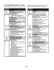
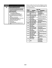
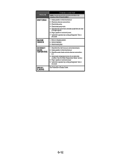
... If too much detergent was used: - Some models do not have the display to the drain pump, pressure switch, and Central Control Unit (CCU). 4. Run a NORMAL cycle without tumbling, the water will rest without adding any cycle. Check wire harness connections to show the failure codes. ..., Rinse, Spin F/33 Add a Garment Add a Garment, Cycle Complete rL Wash Soak/Prewash, Cycle Complete 6-4 Verify CCU operation by the pressure switch during the drain or spin phases, the washer will fill 4 liters of water and during 5 minutes the unit will be drained and it is not plugged or...
... If too much detergent was used: - Some models do not have the display to the drain pump, pressure switch, and Central Control Unit (CCU). 4. Run a NORMAL cycle without tumbling, the water will rest without adding any cycle. Check wire harness connections to show the failure codes. ..., Rinse, Spin F/33 Add a Garment Add a Garment, Cycle Complete rL Wash Soak/Prewash, Cycle Complete 6-4 Verify CCU operation by the pressure switch during the drain or spin phases, the washer will fill 4 liters of water and during 5 minutes the unit will be drained and it is not plugged or...
User Guide
Page 86
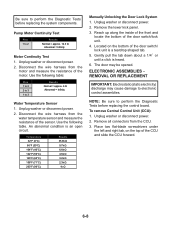
... Sensor 1. Place two flat-blade screwdrivers under the left and right tab, on the bottom of the sensor. Disconnect the wire harness from the CCU. 3. Temperature 32°F (0°C) 86°F (30°C) 104°F (40°C) 122°F (50°C) 140°F (60°C) 158&#...NOTE: Be sure to perform the Diagnostic Tests before replacing the system components. Reach up along the inside of the front and locate the bottom of the door switch/lock unit. 4. Unplug washer or disconnect power. 2. Gently pull the tab down about a 1/4˝ or until a click is an open ...
... Sensor 1. Place two flat-blade screwdrivers under the left and right tab, on the bottom of the sensor. Disconnect the wire harness from the CCU. 3. Temperature 32°F (0°C) 86°F (30°C) 104°F (40°C) 122°F (50°C) 140°F (60°C) 158&#...NOTE: Be sure to perform the Diagnostic Tests before replacing the system components. Reach up along the inside of the front and locate the bottom of the door switch/lock unit. 4. Unplug washer or disconnect power. 2. Gently pull the tab down about a 1/4˝ or until a click is an open ...
User Guide
Page 87
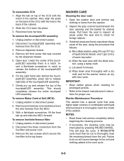
... pressing PAUSE/CANCEL. A RINSE/SPIN cycle must then be interrupted by the dispenser drawer. 5. Unplug washer or disconnect power. 2. Remove dispenser drawer. 4. Insert a flat -blade screwdriver, lift the front tab up and release the top of the touchpad/LED assembly there is a notch. Align the tab... proper use. This will cause damage to the unit and clothing added to release right side of warm tap water. To reassemble CCU: 1. To remove the touchpad/LED assembly: 1. To remove Motor Control Unit (MCU): 1. IMPORTANT: • Wear rubber gloves when cleaning for...
... pressing PAUSE/CANCEL. A RINSE/SPIN cycle must then be interrupted by the dispenser drawer. 5. Unplug washer or disconnect power. 2. Remove dispenser drawer. 4. Insert a flat -blade screwdriver, lift the front tab up and release the top of the touchpad/LED assembly there is a notch. Align the tab... proper use. This will cause damage to the unit and clothing added to release right side of warm tap water. To reassemble CCU: 1. To remove the touchpad/LED assembly: 1. To remove Motor Control Unit (MCU): 1. IMPORTANT: • Wear rubber gloves when cleaning for...
User Guide
Page 89
... drain the unit. 4. Make sure water supply hoses are open. 2. Plug in washer or reconnect power. 8. Unplug washer or disconnect power. 4. Check operating pressure switch. 5. Verify CCU operation by selecting different cycles and changing the modifiers and options available to confirm the ... the door switch/lock unit using the diagnostics. Verify CCU operation by running a Diagnostic Test or any cycle. Verify CCU operation by running a Diagnostic Test or any cycle. Plug in washer or reconnect power. 6. Verify CCU operation by blowing air though the part and measuring the...
... drain the unit. 4. Make sure water supply hoses are open. 2. Plug in washer or reconnect power. 8. Unplug washer or disconnect power. 4. Check operating pressure switch. 5. Verify CCU operation by selecting different cycles and changing the modifiers and options available to confirm the ... the door switch/lock unit using the diagnostics. Verify CCU operation by running a Diagnostic Test or any cycle. Verify CCU operation by running a Diagnostic Test or any cycle. Plug in washer or reconnect power. 6. Verify CCU operation by blowing air though the part and measuring the...
User Guide
Page 90
... condition. MACHINE VIBRATES 1. See the Water Temperature Sensor section . 5. Plug in washer or reconnect power. 7. Verify CCU operation by running a Diagnostic Test or any cycle. Unplug washer or disconnect power. 2. Check water temperature sensor for each problem. 1. Check drain... Remove shipping system. 2. INCORRECT WATER TEMPERATURE 1. Verify CCU operation by running a Diagnostic Test or any cycle. Check the water heater and wire harness connections to it. 4. Check leveling feet. Unplug washer or disconnect power. 3. DISPLAY FLASHING See Failure/Error Display...
... condition. MACHINE VIBRATES 1. See the Water Temperature Sensor section . 5. Plug in washer or reconnect power. 7. Verify CCU operation by running a Diagnostic Test or any cycle. Unplug washer or disconnect power. 2. Check water temperature sensor for each problem. 1. Check drain... Remove shipping system. 2. INCORRECT WATER TEMPERATURE 1. Verify CCU operation by running a Diagnostic Test or any cycle. Check the water heater and wire harness connections to it. 4. Check leveling feet. Unplug washer or disconnect power. 3. DISPLAY FLASHING See Failure/Error Display...
User Guide
Page 91
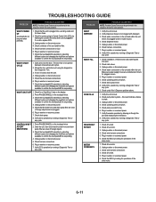
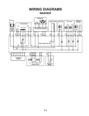
WIRING DIAGRAMS WASHER N L IF DOOR LOCK/SWITCH DS DLS Lock Unlock IF2 DS2 DL3 DLS2 1 2 12 1 2 3 1 2 DRIVE MOTOR MOTOR CONTROL UNIT (MCU) L2 N1 MS2 1 2 MI3 1 2 3 HEATING ELEMENT DRAIN PUMP INLET VALVES DISPENSER Motor Switch VC VH HE2 21 DP2 1 2 VH7 1 3 DI6 571 3 56 DR1 K1 L1 L2 K2 N1 HR2 HR1 CENTRAL CONTROL UNIT (CCU) 12 34 5 6 7 8 UI8 TOUCHPAD/LED ASSEMBLY 6 5 34 PR6 22 24 26 21 2 1 11 14 p> p> L_0 L_wash L_overflow L_sud PRESSURE SWITCH 1 2 TH2 TEMPERATURE SENSOR 7-1
WIRING DIAGRAMS WASHER N L IF DOOR LOCK/SWITCH DS DLS Lock Unlock IF2 DS2 DL3 DLS2 1 2 12 1 2 3 1 2 DRIVE MOTOR MOTOR CONTROL UNIT (MCU) L2 N1 MS2 1 2 MI3 1 2 3 HEATING ELEMENT DRAIN PUMP INLET VALVES DISPENSER Motor Switch VC VH HE2 21 DP2 1 2 VH7 1 3 DI6 571 3 56 DR1 K1 L1 L2 K2 N1 HR2 HR1 CENTRAL CONTROL UNIT (CCU) 12 34 5 6 7 8 UI8 TOUCHPAD/LED ASSEMBLY 6 5 34 PR6 22 24 26 21 2 1 11 14 p> p> L_0 L_wash L_overflow L_sud PRESSURE SWITCH 1 2 TH2 TEMPERATURE SENSOR 7-1
