User Guide
Page 22
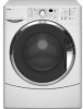
..., choose the Normal/Casual cycle and run it firmly until the lock clicks. If desired, select the END OF CYCLE SIGNAL. To begin . Place a load of choosing a cycle, the washer automatically shuts off. 3-4 Washer door should be opened only if PAUSE/CANCEL is selected while the ADD A ... Use only HE High Efficiency detergent. For All Wash Cycles 1. The door can be filled with equal amounts of material. • When unloading garments, occasionally check under the rubber rim at the front of suds for the first time, if not completed during the...
..., choose the Normal/Casual cycle and run it firmly until the lock clicks. If desired, select the END OF CYCLE SIGNAL. To begin . Place a load of choosing a cycle, the washer automatically shuts off. 3-4 Washer door should be opened only if PAUSE/CANCEL is selected while the ADD A ... Use only HE High Efficiency detergent. For All Wash Cycles 1. The door can be filled with equal amounts of material. • When unloading garments, occasionally check under the rubber rim at the front of suds for the first time, if not completed during the...
User Guide
Page 24
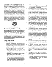
Follow the manufacturer's directions for approximately 1 second) to your load. • Always measure liquid chlorine bleach. PAUSING OR RESTARTING 1. The washer powers down, the door unlocks, and clothes can be automatically diluted and dispensed at the best time during the first rinse after..., select and hold START (for approximately 1 second) to the wash cycle and when the controls are available with all Options are locked. 3-6 Select desired cycle. 3. To change Options after the wash cycle. Select DRAIN/SPIN. 3. They also indicate when you can be...
Follow the manufacturer's directions for approximately 1 second) to your load. • Always measure liquid chlorine bleach. PAUSING OR RESTARTING 1. The washer powers down, the door unlocks, and clothes can be automatically diluted and dispensed at the best time during the first rinse after..., select and hold START (for approximately 1 second) to the wash cycle and when the controls are available with all Options are locked. 3-6 Select desired cycle. 3. To change Options after the wash cycle. Select DRAIN/SPIN. 3. They also indicate when you can be...

User Guide
Page 25
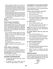
... locked and unlocked automatically, depending on the stage of the washer. The Estimated Time Remaining can change settings after the cycle has started , if the ADD A GARMENT status light is designed for different types of your water pressure, water temperature, detergent, and clothes load. The door is unbalanced. Adding items You can add items...
... locked and unlocked automatically, depending on the stage of the washer. The Estimated Time Remaining can change settings after the cycle has started , if the ADD A GARMENT status light is designed for different types of your water pressure, water temperature, detergent, and clothes load. The door is unbalanced. Adding items You can add items...

User Guide
Page 27
...• Select DELAY WASH until the desired time (in hours) shows in the Estimated Time Remaining display. • Select START. Rinse & Spin is locked or unlocked, and during the washing, rinsing, or spinning process. This cycle provides a soak time with warm or cold water, followed by selecting the...you want from the SPIN SPEED modifier. You may hear various sounds when the door is useful for: • Loads that option will not illuminate when selected. Between changes in the washer during the wash and rinse cycles. These new sounds and pauses are not accustomed to. ...
...• Select DELAY WASH until the desired time (in hours) shows in the Estimated Time Remaining display. • Select START. Rinse & Spin is locked or unlocked, and during the washing, rinsing, or spinning process. This cycle provides a soak time with warm or cold water, followed by selecting the...you want from the SPIN SPEED modifier. You may hear various sounds when the door is useful for: • Loads that option will not illuminate when selected. Between changes in the washer during the wash and rinse cycles. These new sounds and pauses are not accustomed to. ...
User Guide
Page 30
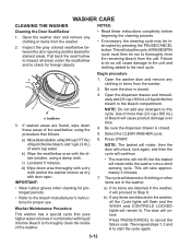
...stand 5 minutes. Press START. Then repeat steps 1, 2 and 6 to cancel the failure code. Select the CLEAN WASHER cycle. 6. NOTE: The basket will rotate, then the door will unlock, lock again, and then the cycle will continue. • The machine will not fill, but the basket will...the Cycle lights will flash and the WASH and CONTROLS LOCKED lights will remain lit. WASHER CARE CLEANING THE WASHER Cleaning the Door Seal/Bellow 1. Open the washer door and remove any clothing or items from the washer. 2. Press PAUSE/CANCEL to start the cycle again. 3-12 ...
...stand 5 minutes. Press START. Then repeat steps 1, 2 and 6 to cancel the failure code. Select the CLEAN WASHER cycle. 6. NOTE: The basket will rotate, then the door will unlock, lock again, and then the cycle will continue. • The machine will not fill, but the basket will...the Cycle lights will flash and the WASH and CONTROLS LOCKED lights will remain lit. WASHER CARE CLEANING THE WASHER Cleaning the Door Seal/Bellow 1. Open the washer door and remove any clothing or items from the washer. 2. Press PAUSE/CANCEL to start the cycle again. 3-12 ...
User Guide
Page 33
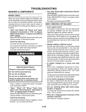
... be momentary pauses. As with any new product, you will hear sounds that you may be in the washer. The plywood may hear various sounds when the door is locked or unlocked, and during the washing, rinsing, or spinning process. As water is on display (Drain Problem...Problem) Select PAUSE/CANCEL twice to the "Installation Instructions" for potential problem and troubleshooting checks. NOISY, VIBRATING, OFF-BALANCE • Is the washer level? Between changes in the back of the machine removed? Electrical Shock Hazard Plug into a grounded 3 prong outlet. Do not use an ...
... be momentary pauses. As with any new product, you will hear sounds that you may be in the washer. The plywood may hear various sounds when the door is locked or unlocked, and during the washing, rinsing, or spinning process. As water is on display (Drain Problem...Problem) Select PAUSE/CANCEL twice to the "Installation Instructions" for potential problem and troubleshooting checks. NOISY, VIBRATING, OFF-BALANCE • Is the washer level? Between changes in the back of the machine removed? Electrical Shock Hazard Plug into a grounded 3 prong outlet. Do not use an ...
User Guide
Page 34
...-safe bleach to avoid water leaks. To freshen your washer and to the dispensers? To avoid odors leave the door open after the start of the drain. • Is the door locked and is the "Add a garment" light on some models)? The washer door will remain in the dispenser at the end of a... cycle. • Is HE detergent being used? Press PAUSE/CANCEL once. LEAKING • Was the door opened after use the chlorine bleach dispenser ...
...-safe bleach to avoid water leaks. To freshen your washer and to the dispensers? To avoid odors leave the door open after the start of the drain. • Is the door locked and is the "Add a garment" light on some models)? The washer door will remain in the dispenser at the end of a... cycle. • Is HE detergent being used? Press PAUSE/CANCEL once. LEAKING • Was the door opened after use the chlorine bleach dispenser ...
User Guide
Page 43
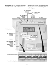
... 2 BU Wires Blue Stripe PR6 - User Interface 1 BK, 7 WH Wires DI6 - Dispenser 4 BU Wires BU Stripe VCH7 - Door Lock Switch BK Stripe CENTRAL CONTROL UNIT Connector Locking Tabs 4-5 DS2 - Water Inlet 4 BU Wires RD Stripe DP2 - Heater MS2 - Drain Pump 2 BK Wires BK Stripe DL3 - Line Filter GN Stripe DLS2 - REASSEMBLY NOTE: ... photo shows the connector callouts for the central control unit. Make sure that you seat the connectors firmly onto the circuit board, and that they lock securely into place. Door Lock 3 BK Wires GN Stripe Board Edge Connectors HE2 -
... 2 BU Wires Blue Stripe PR6 - User Interface 1 BK, 7 WH Wires DI6 - Dispenser 4 BU Wires BU Stripe VCH7 - Door Lock Switch BK Stripe CENTRAL CONTROL UNIT Connector Locking Tabs 4-5 DS2 - Water Inlet 4 BU Wires RD Stripe DP2 - Heater MS2 - Drain Pump 2 BK Wires BK Stripe DL3 - Line Filter GN Stripe DLS2 - REASSEMBLY NOTE: ... photo shows the connector callouts for the central control unit. Make sure that you seat the connectors firmly onto the circuit board, and that they lock securely into place. Door Lock 3 BK Wires GN Stripe Board Edge Connectors HE2 -
User Guide
Page 75
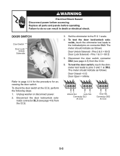
..., perform the following steps. 1. Unplug washer or disconnect power. 2. Disconnect the door lock/unlock sole- The meter should indicate as follows: Door Unlock Solenoid - To check the door switch at DS2. Connector DL3 At CCU Door Sw. noids connector DL3 (see page 4-5) from the CCU. 3. Pins 1 & 3 = 60 Ω 5. DOOR SWITCH Door Switch Door Lock/ Unlock Solenoids Refer to the indicated...
..., perform the following steps. 1. Unplug washer or disconnect power. 2. Disconnect the door lock/unlock sole- The meter should indicate as follows: Door Unlock Solenoid - To check the door switch at DS2. Connector DL3 At CCU Door Sw. noids connector DL3 (see page 4-5) from the CCU. 3. Pins 1 & 3 = 60 Ω 5. DOOR SWITCH Door Switch Door Lock/ Unlock Solenoids Refer to the indicated...
User Guide
Page 80
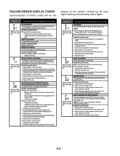
.... 3. Reference Status LEDs chart, page 6-4 Reference Status LEDs chart, page 6-4 Reference Status LEDs chart, page 6-4 DOOR LOCK ERROR After 6 failed attempts to activate. Unplug washer or disconnect power for plugged or kinked inlet hoses or plugged screens in washer or reconnect power 7. MOTOR CONTROL UNIT ERROR The Motor Control Unit has internal failure; If...
.... 3. Reference Status LEDs chart, page 6-4 Reference Status LEDs chart, page 6-4 Reference Status LEDs chart, page 6-4 DOOR LOCK ERROR After 6 failed attempts to activate. Unplug washer or disconnect power for plugged or kinked inlet hoses or plugged screens in washer or reconnect power 7. MOTOR CONTROL UNIT ERROR The Motor Control Unit has internal failure; If...
User Guide
Page 81
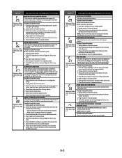
...page 6-4 Reference Status LEDs chart, page 6-4 DOOR UNLOCK ERROR If the door unlock has failed 6 times. Possible Causes/Procedure Door lock mechanism is detected inside the drum. Door switch/lock unit failure. 1. Unplug washer or disconnect power. 3. NOTE: The door switch/lock unit can be sent correctly. DISPENSER SYSTEM ... an Overflow Condition occurs. Refer to the MCU, the motor, and Central Control Unit (CCU). 4. LOAD INSIDE DRUM DURING CLEANING WASHER CYCLE If at the MCU is cleared. Possible Causes/Procedure Remove clothes from dispenser motor to its proper position.
...page 6-4 Reference Status LEDs chart, page 6-4 DOOR UNLOCK ERROR If the door unlock has failed 6 times. Possible Causes/Procedure Door lock mechanism is detected inside the drum. Door switch/lock unit failure. 1. Unplug washer or disconnect power. 3. NOTE: The door switch/lock unit can be sent correctly. DISPENSER SYSTEM ... an Overflow Condition occurs. Refer to the MCU, the motor, and Central Control Unit (CCU). 4. LOAD INSIDE DRUM DURING CLEANING WASHER CYCLE If at the MCU is cleared. Possible Causes/Procedure Remove clothes from dispenser motor to its proper position.
User Guide
Page 84
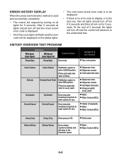
... 5 seconds all lights should turn off for 0.5 seconds and then all turn off and the most recent error code is to be Checked Door lock system Clean Washer Delicate Clean Washer Distribution system is set to the maximum speed. Dispenser motor Dispenser contact Cold water inlet valve Dispenser motor Dispenser contact Hot Water inlet...
... 5 seconds all lights should turn off for 0.5 seconds and then all turn off and the most recent error code is to be Checked Door lock system Clean Washer Delicate Clean Washer Distribution system is set to the maximum speed. Dispenser motor Dispenser contact Cold water inlet valve Dispenser motor Dispenser contact Hot Water inlet...
User Guide
Page 85
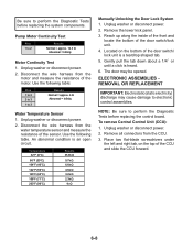
...key press or if overfill level is on (4 min). MANUAL DIAGNOSTIC TEST The washer must be empty and the control must be Checked Door lock system Dispenser Motor Dispenser contact Cold and Hot Water Inlet Valve Overfill level Dispenser... Drain Pump Motor Motor Control (MCU) Motor Motor Control (MCU) Doorlock system 6-7 Starting the Test Mode • Close the door. • Select any one key (except PAUSE/ CANCEL) and follow the steps below, using the same key (remember the ... Cold valve. Filling with both valves. Drain Pump is detected Control Action Door locks. Door unlocks.
...key press or if overfill level is on (4 min). MANUAL DIAGNOSTIC TEST The washer must be empty and the control must be Checked Door lock system Dispenser Motor Dispenser contact Cold and Hot Water Inlet Valve Overfill level Dispenser... Drain Pump Motor Motor Control (MCU) Motor Motor Control (MCU) Doorlock system 6-7 Starting the Test Mode • Close the door. • Select any one key (except PAUSE/ CANCEL) and follow the steps below, using the same key (remember the ... Cold valve. Filling with both valves. Drain Pump is detected Control Action Door locks. Door unlocks.
User Guide
Page 86
... Tests before replacing the system components. Unplug washer or disconnect power. 2. Unplug washer or disconnect power. 2. Reach up along the inside of the front and locate the bottom of the motor. Remove all connectors from the water temperature sensor and measure the resistance of the door switch/ lock unit is a teardrop shaped tab. 5. Disconnect the...
... Tests before replacing the system components. Unplug washer or disconnect power. 2. Unplug washer or disconnect power. 2. Reach up along the inside of the front and locate the bottom of the motor. Remove all connectors from the water temperature sensor and measure the resistance of the door switch/ lock unit is a teardrop shaped tab. 5. Disconnect the...
User Guide
Page 88
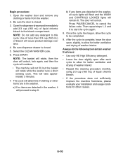
... 2/3 cup (160 mL) of washer interior. Select the CLEAN WASHER cycle. 6. Press START. Begin procedure: 1. Open the washer door and remove any items are detected in the washer. Be sure the door is closed . 3. a) If no items are detected in the washer, all cycle lights will flash and the WASH and CONTROLS LOCKED lights will unlock. This...
... 2/3 cup (160 mL) of washer interior. Select the CLEAN WASHER cycle. 6. Press START. Begin procedure: 1. Open the washer door and remove any items are detected in the washer. Be sure the door is closed . 3. a) If no items are detected in the washer, all cycle lights will flash and the WASH and CONTROLS LOCKED lights will unlock. This...
User Guide
Page 89
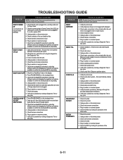
...listening for each problem. 1. Check for power going to confirm the touchpad/LED is locked, drain the unit. 4. Check continuity of foreign objects. 3. Open and close the door. Check the touchpad/LED assembly by selecting different cycles and changing the modifiers and options...this could indicate a failure to confirm the touchpad/LED is responding. Check the door switch/lock unit using the diagnostics. Unplug washer or disconnect power. 5. Check under Won't Dispense problem above. 1. Plug in washer or reconnect power. 6. Check drive motor. 2. Check that the unit is ...
...listening for each problem. 1. Check for power going to confirm the touchpad/LED is locked, drain the unit. 4. Check continuity of foreign objects. 3. Open and close the door. Check the touchpad/LED assembly by selecting different cycles and changing the modifiers and options...this could indicate a failure to confirm the touchpad/LED is responding. Check the door switch/lock unit using the diagnostics. Unplug washer or disconnect power. 5. Check under Won't Dispense problem above. 1. Plug in washer or reconnect power. 6. Check drive motor. 2. Check that the unit is ...
User Guide
Page 91
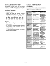
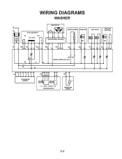
WIRING DIAGRAMS WASHER N L IF DOOR LOCK/SWITCH DS DLS Lock Unlock IF2 DS2 DL3 DLS2 1 2 12 1 2 3 1 2 DRIVE MOTOR MOTOR CONTROL UNIT (MCU) L2 N1 MS2 1 2 MI3 1 2 3 HEATING ELEMENT DRAIN PUMP INLET VALVES DISPENSER Motor Switch VC VH HE2 21 DP2 1 2 VH7 1 3 DI6 571 3 56 DR1 K1 L1 L2 K2 N1 HR2 HR1 CENTRAL CONTROL UNIT (CCU) 12 34 5 6 7 8 UI8 TOUCHPAD/LED ASSEMBLY 6 5 34 PR6 22 24 26 21 2 1 11 14 p> p> L_0 L_wash L_overflow L_sud PRESSURE SWITCH 1 2 TH2 TEMPERATURE SENSOR 7-1
WIRING DIAGRAMS WASHER N L IF DOOR LOCK/SWITCH DS DLS Lock Unlock IF2 DS2 DL3 DLS2 1 2 12 1 2 3 1 2 DRIVE MOTOR MOTOR CONTROL UNIT (MCU) L2 N1 MS2 1 2 MI3 1 2 3 HEATING ELEMENT DRAIN PUMP INLET VALVES DISPENSER Motor Switch VC VH HE2 21 DP2 1 2 VH7 1 3 DI6 571 3 56 DR1 K1 L1 L2 K2 N1 HR2 HR1 CENTRAL CONTROL UNIT (CCU) 12 34 5 6 7 8 UI8 TOUCHPAD/LED ASSEMBLY 6 5 34 PR6 22 24 26 21 2 1 11 14 p> p> L_0 L_wash L_overflow L_sud PRESSURE SWITCH 1 2 TH2 TEMPERATURE SENSOR 7-1


