User Guide
Page 43
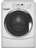
... - Drive Motor WH Stripe IF2 - Door Lock Switch BK Stripe CENTRAL CONTROL UNIT Connector Locking Tabs 4-5 Door Lock 3 BK Wires GN Stripe Board Edge Connectors HE2 - Door Switch 2 BU Wires Blue Stripe PR6 - Temp Sensor 2 BK Wires Not Used No Stripe MI3 Serial Com 3 BU Wires Red Stripe Not Used UI8...
... - Drive Motor WH Stripe IF2 - Door Lock Switch BK Stripe CENTRAL CONTROL UNIT Connector Locking Tabs 4-5 Door Lock 3 BK Wires GN Stripe Board Edge Connectors HE2 - Door Switch 2 BU Wires Blue Stripe PR6 - Temp Sensor 2 BK Wires Not Used No Stripe MI3 Serial Com 3 BU Wires Red Stripe Not Used UI8...

User Guide
Page 77
...The meter should indicate between 10 and 15 Ω. Disconnect the temperature sensor connector TH2 (see page 4-5) from the CCU. 3. Unplug washer or disconnect power. 2. Connector HE2 At CCU 1 2 5-7 Failure to the R X 1K scale. 4. Set the ohmmeter to do so can result in death or ...touch the ohmmeter test leads to connector pins 1 and 2. Touch the ohmmeter test leads to the R X 1 scale. 4. Disconnect the heater connector HE2 (see page 4-5) from the temperature sensor or heater. 3. Set the ohmmeter to connector pins 1 and 2. Replace all parts and panels before accessing...
...The meter should indicate between 10 and 15 Ω. Disconnect the temperature sensor connector TH2 (see page 4-5) from the CCU. 3. Unplug washer or disconnect power. 2. Connector HE2 At CCU 1 2 5-7 Failure to the R X 1K scale. 4. Set the ohmmeter to do so can result in death or ...touch the ohmmeter test leads to connector pins 1 and 2. Touch the ohmmeter test leads to the R X 1 scale. 4. Disconnect the heater connector HE2 (see page 4-5) from the temperature sensor or heater. 3. Set the ohmmeter to connector pins 1 and 2. Replace all parts and panels before accessing...
User Guide
Page 91
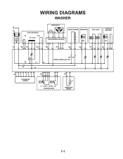
WIRING DIAGRAMS WASHER N L IF DOOR LOCK/SWITCH DS DLS Lock Unlock IF2 DS2 DL3 DLS2 1 2 12 1 2 3 1 2 DRIVE MOTOR MOTOR CONTROL UNIT (MCU) L2 N1 MS2 1 2 MI3 1 2 3 HEATING ELEMENT DRAIN PUMP INLET VALVES DISPENSER Motor Switch VC VH HE2 21 DP2 1 2 VH7 1 3 DI6 571 3 56 DR1 K1 L1 L2 K2 N1 HR2 HR1 CENTRAL CONTROL UNIT (CCU) 12 34 5 6 7 8 UI8 TOUCHPAD/LED ASSEMBLY 6 5 34 PR6 22 24 26 21 2 1 11 14 p> p> L_0 L_wash L_overflow L_sud PRESSURE SWITCH 1 2 TH2 TEMPERATURE SENSOR 7-1
WIRING DIAGRAMS WASHER N L IF DOOR LOCK/SWITCH DS DLS Lock Unlock IF2 DS2 DL3 DLS2 1 2 12 1 2 3 1 2 DRIVE MOTOR MOTOR CONTROL UNIT (MCU) L2 N1 MS2 1 2 MI3 1 2 3 HEATING ELEMENT DRAIN PUMP INLET VALVES DISPENSER Motor Switch VC VH HE2 21 DP2 1 2 VH7 1 3 DI6 571 3 56 DR1 K1 L1 L2 K2 N1 HR2 HR1 CENTRAL CONTROL UNIT (CCU) 12 34 5 6 7 8 UI8 TOUCHPAD/LED ASSEMBLY 6 5 34 PR6 22 24 26 21 2 1 11 14 p> p> L_0 L_wash L_overflow L_sud PRESSURE SWITCH 1 2 TH2 TEMPERATURE SENSOR 7-1

