User Guide
Page 6
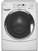
MODEL & SERIAL NUMBER DESIGNATIONS MODEL NUMBER MODEL NUMBER W F W 8 3 00 S W 0 BRAND W = Whirlpool ACCESS F = Front Loading PRODUCT W = Washer SERIES 5 = Whirlpool Leap 7 = 24˝ Front Load 9 = Duet Front Load 6 = Oasis 8 = Mid Line Front Load PRICE POINT LEVELS (1 - 9) TRADE PARTNER ID (00 = BRANDED) YEAR OF INTRODUCTION S = 2006, T = 2007 COLOR CODE T = Biscuit Q = White W = White With Metallic Accent R = White With Metallic (Sport ...
MODEL & SERIAL NUMBER DESIGNATIONS MODEL NUMBER MODEL NUMBER W F W 8 3 00 S W 0 BRAND W = Whirlpool ACCESS F = Front Loading PRODUCT W = Washer SERIES 5 = Whirlpool Leap 7 = 24˝ Front Load 9 = Duet Front Load 6 = Oasis 8 = Mid Line Front Load PRICE POINT LEVELS (1 - 9) TRADE PARTNER ID (00 = BRANDED) YEAR OF INTRODUCTION S = 2006, T = 2007 COLOR CODE T = Biscuit Q = White W = White With Metallic Accent R = White With Metallic (Sport ...
User Guide
Page 11
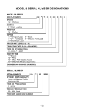
...24 in the top are required. 7" (17.8 cm) 7" (17.8 cm) 9" (22.9 cm) 4" 31¹⁄2" 1" 1" 27" 1" (10.2 cm) (80.0 cm) (2.5 cm) (2.5 cm) (68.6 cm) (2.5 cm) 2-3 Recommended installation spacing for cabinet installation The dimensions shown are for the recommended spacing. For cabinet installation with vents Recessed or closet installation Washer...cm) A B A. closet or confined area B. Recommended installation spacing for recessed or closet installation, with stacked washer and dryer The dimensions shown, at the top of the right column, are for the recommended spacing. 72...
...24 in the top are required. 7" (17.8 cm) 7" (17.8 cm) 9" (22.9 cm) 4" 31¹⁄2" 1" 1" 27" 1" (10.2 cm) (80.0 cm) (2.5 cm) (2.5 cm) (68.6 cm) (2.5 cm) 2-3 Recommended installation spacing for cabinet installation The dimensions shown are for the recommended spacing. For cabinet installation with vents Recessed or closet installation Washer...cm) A B A. closet or confined area B. Recommended installation spacing for recessed or closet installation, with stacked washer and dryer The dimensions shown, at the top of the right column, are for the recommended spacing. 72...

User Guide
Page 62
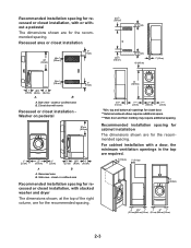
d) Rotate the motor down and pull it toward you so the bracket studs are out of the tub mounting holes, and remove the motor. Drive Motor Studs Drive Motor Drive Motor 4-24
d) Rotate the motor down and pull it toward you so the bracket studs are out of the tub mounting holes, and remove the motor. Drive Motor Studs Drive Motor Drive Motor 4-24
User Guide
Page 70
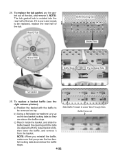
..., and remove it from the basket. If it is molded into the rear half of the tub. b) Using a flat-blade screwdriver, pry up on top. 24. NOTE: The tub gasket hub is worn and needs to be removed on the two basket locking tabs so they are aligned with the baffle...
..., and remove it from the basket. If it is molded into the rear half of the tub. b) Using a flat-blade screwdriver, pry up on top. 24. NOTE: The tub gasket hub is worn and needs to be removed on the two basket locking tabs so they are aligned with the baffle...
User Guide
Page 82
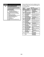
...Spin F/22 Wash, Rinse, Cycle Complete Soak/Prewash, Wash, Spin F/23 Add a Garment, Wash, Rinse, Cycle Complete Add a Garment, Soak/Prewash, Wash, Spin F/24 Spin, Cycle Complete Rinse, Spin F/25 Add a Garment, Spin, Cycle Complete Add a Garment, Rinse, Spin, F/26 Wash, Spin, Cycle Complete Soak/Prewash, Rinse,... 6. They use the status lights on the touchpad/LED. This should clear the unit of water and during the drain or spin phases, the washer will fill 4 liters of the excess detergent. 1. Check the pressure switch. 8. Run the unit through a RINSE/SPIN cycle. - Check/clean...
...Spin F/22 Wash, Rinse, Cycle Complete Soak/Prewash, Wash, Spin F/23 Add a Garment, Wash, Rinse, Cycle Complete Add a Garment, Soak/Prewash, Wash, Spin F/24 Spin, Cycle Complete Rinse, Spin F/25 Add a Garment, Spin, Cycle Complete Add a Garment, Rinse, Spin, F/26 Wash, Spin, Cycle Complete Soak/Prewash, Rinse,... 6. They use the status lights on the touchpad/LED. This should clear the unit of water and during the drain or spin phases, the washer will fill 4 liters of the excess detergent. 1. Check the pressure switch. 8. Run the unit through a RINSE/SPIN cycle. - Check/clean...
User Guide
Page 91
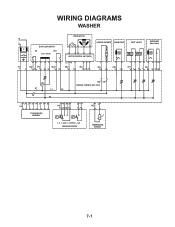
WIRING DIAGRAMS WASHER N L IF DOOR LOCK/SWITCH DS DLS Lock Unlock IF2 DS2 DL3 DLS2 1 2 12 1 2 3 1 2 DRIVE MOTOR MOTOR CONTROL UNIT (MCU) L2 N1 MS2 1 2 MI3 1 2 3 HEATING ELEMENT DRAIN PUMP INLET VALVES DISPENSER Motor Switch VC VH HE2 21 DP2 1 2 VH7 1 3 DI6 571 3 56 DR1 K1 L1 L2 K2 N1 HR2 HR1 CENTRAL CONTROL UNIT (CCU) 12 34 5 6 7 8 UI8 TOUCHPAD/LED ASSEMBLY 6 5 34 PR6 22 24 26 21 2 1 11 14 p> p> L_0 L_wash L_overflow L_sud PRESSURE SWITCH 1 2 TH2 TEMPERATURE SENSOR 7-1
WIRING DIAGRAMS WASHER N L IF DOOR LOCK/SWITCH DS DLS Lock Unlock IF2 DS2 DL3 DLS2 1 2 12 1 2 3 1 2 DRIVE MOTOR MOTOR CONTROL UNIT (MCU) L2 N1 MS2 1 2 MI3 1 2 3 HEATING ELEMENT DRAIN PUMP INLET VALVES DISPENSER Motor Switch VC VH HE2 21 DP2 1 2 VH7 1 3 DI6 571 3 56 DR1 K1 L1 L2 K2 N1 HR2 HR1 CENTRAL CONTROL UNIT (CCU) 12 34 5 6 7 8 UI8 TOUCHPAD/LED ASSEMBLY 6 5 34 PR6 22 24 26 21 2 1 11 14 p> p> L_0 L_wash L_overflow L_sud PRESSURE SWITCH 1 2 TH2 TEMPERATURE SENSOR 7-1


