User Guide
Page 3
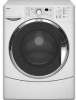
... And Tech Sheet Locations 1-3 Specifications 1-4 INSTALLATION INFORMATION 2-1 Installation Requirements 2-1 Installation Instructions 2-6 PRODUCT OPERATION 3-1 Features And Benefits 3-1 Washer Use 3-3 Washer Care 3-12 Troubleshooting 3-15 COMPONENT ACCESS 4-1 Component Locations 4-1 Removing The Console And The Touchpad/LED Assembly 4-2 Removing The Central ... The Drain Pump 4-17 Removing The ECO Valve 4-19 Removing The Motor Control Unit 4-20 Removing The Temperature Sensor & Heater 4-22 Removing The Drive Belt And Motor 4-23 Removing An Interlock Switch 4-25 Removing The ...
... And Tech Sheet Locations 1-3 Specifications 1-4 INSTALLATION INFORMATION 2-1 Installation Requirements 2-1 Installation Instructions 2-6 PRODUCT OPERATION 3-1 Features And Benefits 3-1 Washer Use 3-3 Washer Care 3-12 Troubleshooting 3-15 COMPONENT ACCESS 4-1 Component Locations 4-1 Removing The Console And The Touchpad/LED Assembly 4-2 Removing The Central ... The Drain Pump 4-17 Removing The ECO Valve 4-19 Removing The Motor Control Unit 4-20 Removing The Temperature Sensor & Heater 4-22 Removing The Drive Belt And Motor 4-23 Removing An Interlock Switch 4-25 Removing The ...
User Guide
Page 8
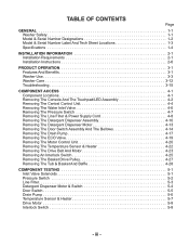
...Cu.Ft. Max Width Product Weight (approx) WFW8300SW WFW8500SW WFW8500SR Front Load Washer Front Load Washer Front Load Washer White with Gray Accents White with Gray Accents White with Sterling Bright Accents 3.3 3.6 3.6 ATC - 2 ATC - 4 ATC - 4 No Yes Yes Suds Sensor, NTC (Thermistor), Water Level Sensor Suds Sensor, NTC (Thermistor), Water Level Sensor Suds Sensor, NTC (Thermistor), Water Level Sensor... 30.00" 27" 242 lbs. 1-4 IEC) Temperature Control Heater Sensors Tumble Speed Spin Speed Motor Voltage Frequency Amps Water Consumption Average DOE (Gallons-Per-Cycle) Rated...
...Cu.Ft. Max Width Product Weight (approx) WFW8300SW WFW8500SW WFW8500SR Front Load Washer Front Load Washer Front Load Washer White with Gray Accents White with Gray Accents White with Sterling Bright Accents 3.3 3.6 3.6 ATC - 2 ATC - 4 ATC - 4 No Yes Yes Suds Sensor, NTC (Thermistor), Water Level Sensor Suds Sensor, NTC (Thermistor), Water Level Sensor Suds Sensor, NTC (Thermistor), Water Level Sensor... 30.00" 27" 242 lbs. 1-4 IEC) Temperature Control Heater Sensors Tumble Speed Spin Speed Motor Voltage Frequency Amps Water Consumption Average DOE (Gallons-Per-Cycle) Rated...
User Guide
Page 39
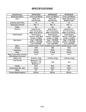
COMPONENT LOCATIONS Water Inlet Valve Line Filter Detergent Dispenser Motor & Assembly Pressure Switch Central Control Unit Temperature Sensor (On Rear Of Tub) Heater (On Rear Of Tub) Basket Tub Assembly Drive Motor Front Interlock Switch Not Shown: Console, Touchpad/LED Assembly, & Door Switch Assembly Rear Interlock Switch ECO Valve Motor Control Unit Drain Pump 4-1 The components and their locations are shown below. COMPONENT ACCESS This section instructs you on how to service each component inside the Duet Sport™ Front-Loading Automatic Washer.
COMPONENT LOCATIONS Water Inlet Valve Line Filter Detergent Dispenser Motor & Assembly Pressure Switch Central Control Unit Temperature Sensor (On Rear Of Tub) Heater (On Rear Of Tub) Basket Tub Assembly Drive Motor Front Interlock Switch Not Shown: Console, Touchpad/LED Assembly, & Door Switch Assembly Rear Interlock Switch ECO Valve Motor Control Unit Drain Pump 4-1 The components and their locations are shown below. COMPONENT ACCESS This section instructs you on how to service each component inside the Duet Sport™ Front-Loading Automatic Washer.

User Guide
Page 60
... remove the temperature sensor: a) Disconnect the wire connector from the wall. 4. Pull Temperature Sensor Out Of Heater 6. Heater Temperature Sensor Wire Connector 4-22 REMOVING THE TEMPERATURE SENSOR & HEATER b) Loosen the 10 mm nut and pull the temperature sensor out of the tub opening. Replace all parts and panels before servicing. Pull the washer away from the temperature sensor. Temperature Sensor & Heater Temperature Sensor & Heater 5. Unplug washer or disconnect...
... remove the temperature sensor: a) Disconnect the wire connector from the wall. 4. Pull Temperature Sensor Out Of Heater 6. Heater Temperature Sensor Wire Connector 4-22 REMOVING THE TEMPERATURE SENSOR & HEATER b) Loosen the 10 mm nut and pull the temperature sensor out of the tub opening. Replace all parts and panels before servicing. Pull the washer away from the temperature sensor. Temperature Sensor & Heater Temperature Sensor & Heater 5. Unplug washer or disconnect...

User Guide
Page 68
... tub and basket assembly and unhook the two suspension springs, then remove the assembly from the washer, and place it contacts the bracket, then turn the nut an additional 1/4-turn the top ...locking tabs align with the slots in the base mounting brackets, tighten the nut until it front-side down on the standoff tabs to release the standoffs. Remove the drive motor from the...wiring standoffs from the tub. 23. 18. Remove the four shock absorbers from the base. Remove the temperature sensor and heater from the tub (see page 4-22 for the procedure). 19. To remove a shock absorber...
... tub and basket assembly and unhook the two suspension springs, then remove the assembly from the washer, and place it contacts the bracket, then turn the nut an additional 1/4-turn the top ...locking tabs align with the slots in the base mounting brackets, tighten the nut until it front-side down on the standoff tabs to release the standoffs. Remove the drive motor from the...wiring standoffs from the tub. 23. 18. Remove the four shock absorbers from the base. Remove the temperature sensor and heater from the tub (see page 4-22 for the procedure). 19. To remove a shock absorber...

User Guide
Page 77
... do so can result in death or electrical shock. Disconnect the temperature sensor connector TH2 (see page 4-5) from the temperature sensor or heater. 3. Unplug washer or disconnect power. 2. To check the temperature sensor, touch the ohmmeter test leads to the R X 1 scale. 4. Set the ohmmeter to the sensor terminals. Set the ohmmeter to connector pins 1 and 2. Touch the ohmmeter...
... do so can result in death or electrical shock. Disconnect the temperature sensor connector TH2 (see page 4-5) from the temperature sensor or heater. 3. Unplug washer or disconnect power. 2. To check the temperature sensor, touch the ohmmeter test leads to the R X 1 scale. 4. Set the ohmmeter to the sensor terminals. Set the ohmmeter to connector pins 1 and 2. Touch the ohmmeter...
User Guide
Page 80
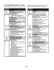
... PAUSE/CANCEL twice to clear the display. Possible Causes/Procedure 1. Check door switch/lock unit. 3. Unplug washer or disconnect power. 2. Check the water temperature sensor and connection to tub and pressure switch. 1. played on all the way. - MOTOR CONTROL UNIT ERROR The... . 3. Check resistance of the drive motor. 5. WATER TEMPERATURE SENSOR ERROR If the water temperature sensor (NTC) value is out of heating element, if present on this error. - Plug in washer or reconnect power. 6. Plug in washer or reconnect power. 4. Check the wire harness connections to water...
... PAUSE/CANCEL twice to clear the display. Possible Causes/Procedure 1. Check door switch/lock unit. 3. Unplug washer or disconnect power. 2. Check the water temperature sensor and connection to tub and pressure switch. 1. played on all the way. - MOTOR CONTROL UNIT ERROR The... . 3. Check resistance of the drive motor. 5. WATER TEMPERATURE SENSOR ERROR If the water temperature sensor (NTC) value is out of heating element, if present on this error. - Plug in washer or reconnect power. 6. Plug in washer or reconnect power. 4. Check the wire harness connections to water...
User Guide
Page 86
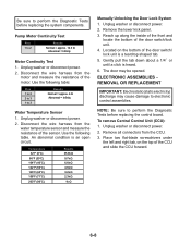
...front and locate the bottom of the motor. ELECTRONIC ASSEMBLIES REMOVAL OR REPLACEMENT IMPORTANT: Electrostatic (static electricity) discharge may be opened. Remove all connectors from the water temperature sensor and measure the resistance of the sensor. Pump Motor Continuity Test Pins 1 to 2 Results Normal = approx. 12.3 Ω Abnormal = Infinity Motor Continuity Test 1. Unplug washer...2 to 3 1 to 3 Results Normal = approx. 6 Ω Abnormal = Infinity Water Temperature Sensor 1. To remove Central Control Unit (CCU): 1. Be sure to perform the Diagnostic Tests before replacing the ...
...front and locate the bottom of the motor. ELECTRONIC ASSEMBLIES REMOVAL OR REPLACEMENT IMPORTANT: Electrostatic (static electricity) discharge may be opened. Remove all connectors from the water temperature sensor and measure the resistance of the sensor. Pump Motor Continuity Test Pins 1 to 2 Results Normal = approx. 12.3 Ω Abnormal = Infinity Motor Continuity Test 1. Unplug washer...2 to 3 1 to 3 Results Normal = approx. 6 Ω Abnormal = Infinity Water Temperature Sensor 1. To remove Central Control Unit (CCU): 1. Be sure to perform the Diagnostic Tests before replacing the ...
User Guide
Page 90
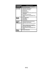
... operation by running a Diagnostic Test or any cycle. MACHINE VIBRATES 1. Check water temperature sensor for each problem. 1. Verify CCU operation by running a Diagnostic Test or any cycle. Unplug washer or disconnect power. 2. Check that the inlet hoses are clear of foreign objects.... 6. Check that the drain hose and drain pump filter are connected properly. 2. Remove shipping system. 2. Unplug washer or disconnect power. 3. See the Water Temperature Sensor section . 5. Check drain pump motor. 5. Check the water heater and wire harness connections to it. 4. Check...
... operation by running a Diagnostic Test or any cycle. MACHINE VIBRATES 1. Check water temperature sensor for each problem. 1. Verify CCU operation by running a Diagnostic Test or any cycle. Unplug washer or disconnect power. 2. Check that the inlet hoses are clear of foreign objects.... 6. Check that the drain hose and drain pump filter are connected properly. 2. Remove shipping system. 2. Unplug washer or disconnect power. 3. See the Water Temperature Sensor section . 5. Check drain pump motor. 5. Check the water heater and wire harness connections to it. 4. Check...
User Guide
Page 91
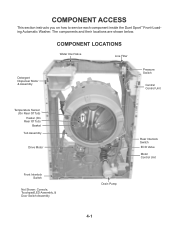
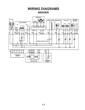
WIRING DIAGRAMS WASHER N L IF DOOR LOCK/SWITCH DS DLS Lock Unlock IF2 DS2 DL3 DLS2 1 2 12 1 2 3 1 2 DRIVE MOTOR MOTOR CONTROL UNIT (MCU) L2 N1 MS2 1 2 MI3 1 2 3 HEATING ELEMENT DRAIN PUMP INLET VALVES DISPENSER Motor Switch VC VH HE2 21 DP2 1 2 VH7 1 3 DI6 571 3 56 DR1 K1 L1 L2 K2 N1 HR2 HR1 CENTRAL CONTROL UNIT (CCU) 12 34 5 6 7 8 UI8 TOUCHPAD/LED ASSEMBLY 6 5 34 PR6 22 24 26 21 2 1 11 14 p> p> L_0 L_wash L_overflow L_sud PRESSURE SWITCH 1 2 TH2 TEMPERATURE SENSOR 7-1
WIRING DIAGRAMS WASHER N L IF DOOR LOCK/SWITCH DS DLS Lock Unlock IF2 DS2 DL3 DLS2 1 2 12 1 2 3 1 2 DRIVE MOTOR MOTOR CONTROL UNIT (MCU) L2 N1 MS2 1 2 MI3 1 2 3 HEATING ELEMENT DRAIN PUMP INLET VALVES DISPENSER Motor Switch VC VH HE2 21 DP2 1 2 VH7 1 3 DI6 571 3 56 DR1 K1 L1 L2 K2 N1 HR2 HR1 CENTRAL CONTROL UNIT (CCU) 12 34 5 6 7 8 UI8 TOUCHPAD/LED ASSEMBLY 6 5 34 PR6 22 24 26 21 2 1 11 14 p> p> L_0 L_wash L_overflow L_sud PRESSURE SWITCH 1 2 TH2 TEMPERATURE SENSOR 7-1


