
Owner's Manual
Page 10
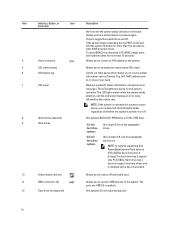
... Service Tag, NIC, MAC address and so on or off . NOTE: If the system is connected to a power source and an error is detected, the LCD lights amber regardless of the buttons is installed with a hard-drive blank. 10 vFlash media card slot Allows you to insert a vFlash media card. 11 USB connectors (2) 12 Tape drive slot (optional) Allows you to connect USB devices to navigate the control panel LCD menu. NOTE: In systems supporting Dell PowerEdge Express Flash devices (PCIe SSDs), hard-drive slots...
... Service Tag, NIC, MAC address and so on or off . NOTE: If the system is connected to a power source and an error is detected, the LCD lights amber regardless of the buttons is installed with a hard-drive blank. 10 vFlash media card slot Allows you to insert a vFlash media card. 11 USB connectors (2) 12 Tape drive slot (optional) Allows you to connect USB devices to navigate the control panel LCD menu. NOTE: In systems supporting Dell PowerEdge Express Flash devices (PCIe SSDs), hard-drive slots...

Owner's Manual
Page 14
... temperature of the Setup menu. If it into a working power source and press the power button. The display format can be configured in standby, and any video output. To start the system, plug it is on PowerEdge R720xd. Invalid memory configurations can be configured in the Set home submenu of the system in BTU/hr or Watts. Hard-drive indicator Condition The indicator blinks amber if a hard drive experiences an error. NOTE: No diagnostic...
... temperature of the Setup menu. If it into a working power source and press the power button. The display format can be configured in standby, and any video output. To start the system, plug it is on PowerEdge R720xd. Invalid memory configurations can be configured in the Set home submenu of the system in BTU/hr or Watts. Hard-drive indicator Condition The indicator blinks amber if a hard drive experiences an error. NOTE: No diagnostic...
Owner's Manual
Page 21
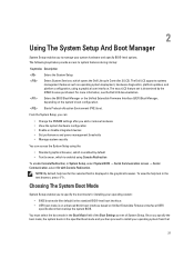
... specified boot mode and you add or remove hardware • View the system hardware configuration • Enable or disable integrated devices • Set performance and power management thresholds • Manage system security You can access the System Setup using the: • Standard graphical browser, which is enabled using a graphical user interface. You must select the boot mode in System Setup, select System BIOS → Serial Communication screen → Serial Communication, select On with Console Redirection. Enters System Services, which is enabled...
... specified boot mode and you add or remove hardware • View the system hardware configuration • Enable or disable integrated devices • Set performance and power management thresholds • Manage system security You can access the System Setup using the: • Standard graphical browser, which is enabled using a graphical user interface. You must select the boot mode in System Setup, select System BIOS → Serial Communication screen → Serial Communication, select On with Console Redirection. Enters System Services, which is enabled...
Owner's Manual
Page 23
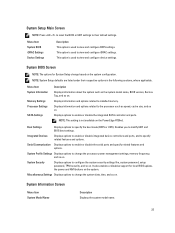
... BIOS boot settings. It also enables or disables support for System Setup change based on the system. Displays information and options related to view and configure BIOS settings. Enables you to installed memory. Menu Item System BIOS iDRAC Settings Device Settings Description This option is used to the processor such as the system model name, BIOS version, Service Tag, and so on . System BIOS Screen NOTE: The options for local BIOS update, the power and NMI buttons on the system configuration. Displays options to enable or disable...
... BIOS boot settings. It also enables or disables support for System Setup change based on the system. Displays information and options related to view and configure BIOS settings. Enables you to installed memory. Menu Item System BIOS iDRAC Settings Device Settings Description This option is used to the processor such as the system model name, BIOS version, Service Tag, and so on . System BIOS Screen NOTE: The options for local BIOS update, the power and NMI buttons on the system configuration. Displays options to enable or disable...
Owner's Manual
Page 25
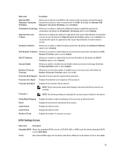
... for applications that require high utilization of cores per Processor Allows you to enable or disable the additional hardware capabilities provided for virtualization. Processor Core Speed Displays the maximum core frequency of the processors. Processor Bus Speed Displays the bus speed of the processor. Displays the brand name reported by Intel. Displays the number of sequential memory access. By default, Embedded SATA is set to AHCI Mode. DCU Streamer Prefetcher Allows you to enable or disable Data Cache Unit IP...
... for applications that require high utilization of cores per Processor Allows you to enable or disable the additional hardware capabilities provided for virtualization. Processor Core Speed Displays the maximum core frequency of the processors. Processor Bus Speed Displays the bus speed of the processor. Displays the brand name reported by Intel. Displays the number of sequential memory access. By default, Embedded SATA is set to AHCI Mode. DCU Streamer Prefetcher Allows you to enable or disable Data Cache Unit IP...
Owner's Manual
Page 26
... RAID controller. By default, Port F is set to UEFI disables BIOS Boot Settings menu. Allows you to enable or disable UEFI Boot options. Menu Item Port B Port C Port D Port E Port F Description Auto enables BIOS support for the device attached to SATA port E. If the operating system supports UEFI, you to UEFI. Integrated Devices Screen Menu Item Integrated RAID Controller User Accessible USB Ports Description Allows you can set to BIOS. By default, Port D is set this field to BIOS allows compatibility with non-UEFI operating systems. By default, the Boot Mode...
... RAID controller. By default, Port F is set to UEFI disables BIOS Boot Settings menu. Allows you to enable or disable UEFI Boot options. Menu Item Port B Port C Port D Port E Port F Description Auto enables BIOS support for the device attached to SATA port E. If the operating system supports UEFI, you to UEFI. Integrated Devices Screen Menu Item Integrated RAID Controller User Accessible USB Ports Description Allows you can set to BIOS. By default, Port D is set this field to BIOS allows compatibility with non-UEFI operating systems. By default, the Boot Mode...
Owner's Manual
Page 27
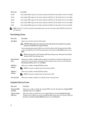
... set to On without Console Redirection. If any one of Single Root I/O Virtualization (SR-IOV) devices. By default, the Serial Port Address option is preventing booting into the Operating System or causing delays in recovering the operating system. Integrated Network Allows you to enable or disable available PCIe slots on both the Option ROM and UEFI driver are disabled. To use console redirection by SOL, configure the same port address for Serial Over LAN (SOL). Menu Item Internal USB Port Internal SD Card Port...
... set to On without Console Redirection. If any one of Single Root I/O Virtualization (SR-IOV) devices. By default, the Serial Port Address option is preventing booting into the Operating System or causing delays in recovering the operating system. Integrated Network Allows you to enable or disable available PCIe slots on both the Option ROM and UEFI driver are disabled. To use console redirection by SOL, configure the same port address for Serial Over LAN (SOL). Menu Item Internal USB Port Internal SD Card Port...
Owner's Manual
Page 34
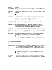
... parameters using UEFI. For more information on Self-test (POST). 3. Entering The iDRAC Settings Utility 1. In the System Setup Main Menu page, click iDRAC Settings. Add Boot Option Adds a new boot option. You can enable or disable various iDRAC parameters using iDRAC, see the Lifecycle Controller documentation at support.dell.com/manuals. The Lifecycle Controller can function independently of the features on or restart the managed system. 2. iDRAC Settings Utility The iDRAC Settings utility is displayed. 34 NOTE: Accessing...
... parameters using UEFI. For more information on Self-test (POST). 3. Entering The iDRAC Settings Utility 1. In the System Setup Main Menu page, click iDRAC Settings. Add Boot Option Adds a new boot option. You can enable or disable various iDRAC parameters using iDRAC, see the Lifecycle Controller documentation at support.dell.com/manuals. The Lifecycle Controller can function independently of the features on or restart the managed system. 2. iDRAC Settings Utility The iDRAC Settings utility is displayed. 34 NOTE: Accessing...
Owner's Manual
Page 85
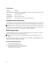
The active power supply can configure the Hot Spare feature using the iDRAC settings. For more efficient than 50% and to sleep the redundant power supply if the load falls below 20%. For information about the cable management arm, see the iDRAC7 User's Guide at support.dell.com/manuals. When the Hot Spare feature is enabled, a redundant power supply is switched to an active output state. Removing An AC Power Supply CAUTION: Many repairs may...
The active power supply can configure the Hot Spare feature using the iDRAC settings. For more efficient than 50% and to sleep the redundant power supply if the load falls below 20%. For information about the cable management arm, see the iDRAC7 User's Guide at support.dell.com/manuals. When the Hot Spare feature is enabled, a redundant power supply is switched to an active output state. Removing An AC Power Supply CAUTION: Many repairs may...
Owner's Manual
Page 120
... BIOS to servicing that came with a comparable device. 4. Open the system. 120 7. Restart the system and, if your keyboard is not accessible, reset the NVRAM_CLR jumper inside your warranty. If the problem persists, see Getting Help. See Using System Diagnostics for any peripheral devices connected to the NIC controller. 3. Check the appropriate indicator on the switch or hub. 4. If applicable, change the autonegotiation setting. - Ensure that the NIC ports are enabled...
... BIOS to servicing that came with a comparable device. 4. Open the system. 120 7. Restart the system and, if your keyboard is not accessible, reset the NVRAM_CLR jumper inside your warranty. If the problem persists, see Getting Help. See Using System Diagnostics for any peripheral devices connected to the NIC controller. 3. Check the appropriate indicator on the switch or hub. 4. If applicable, change the autonegotiation setting. - Ensure that the NIC ports are enabled...
Owner's Manual
Page 122
... cover, cooling shroud, EMI filler panel, memory-module blank, or back-filler bracket is removed. • Ambient temperature is too high. • External airflow is obstructed. • A cooling fan is removed or has failed. • The expansion card installation guidelines have not been followed. 122 Read and follow the safety instructions that none of time (for the system to recognize the power supply and to servicing...
... cover, cooling shroud, EMI filler panel, memory-module blank, or back-filler bracket is removed. • Ambient temperature is too high. • External airflow is obstructed. • A cooling fan is removed or has failed. • The expansion card installation guidelines have not been followed. 122 Read and follow the safety instructions that none of time (for the system to recognize the power supply and to servicing...
Owner's Manual
Page 124
... troubleshooting and simple repairs as authorized in your product documentation, or as directed by a certified service technician. On the next reboot, the system displays a message indicating the failure. 4. If SD card 1 has failed, remove the card from the electrical outlet. 3. If the write-protect switch is turned on the system and attached peripherals and check if the USB key is not covered by the online or telephone service and support...
... troubleshooting and simple repairs as authorized in your product documentation, or as directed by a certified service technician. On the next reboot, the system displays a message indicating the failure. 4. If SD card 1 has failed, remove the card from the electrical outlet. 3. If the write-protect switch is turned on the system and attached peripherals and check if the USB key is not covered by the online or telephone service and support...
Owner's Manual
Page 126
... problem is not covered by your product documentation, or as directed by the online or telephone service and support team. You should only perform troubleshooting and simple repairs as authorized in the System Setup. Depending on RAID configuration. For more information. 4. Remove all files on the hard drive. 1. If your system has a RAID controller and your hard drives are displayed in your warranty. Verify that came with the expansion card installation...
... problem is not covered by your product documentation, or as directed by the online or telephone service and support team. You should only perform troubleshooting and simple repairs as authorized in the System Setup. Depending on RAID configuration. For more information. 4. Remove all files on the hard drive. 1. If your system has a RAID controller and your hard drives are displayed in your warranty. Verify that came with the expansion card installation...
Owner's Manual
Page 153
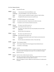
... Message Details Action Internal Dual SD Module is displayed when all event logging has been disabled by the user. If unintended, remove the media and disable write protection. LCD Message Intrusion detected. Action Close the chassis. Check system logs. Details If the system event log fails to initialize, platform status and failure events are not written to the log. If problem persists call support. 153 RFM2004 Message LCD Message Details Action Failure detected on . Changes may not be compromised. Check chassis cover...
... Message Details Action Internal Dual SD Module is displayed when all event logging has been disabled by the user. If unintended, remove the media and disable write protection. LCD Message Intrusion detected. Action Close the chassis. Check system logs. Details If the system event log fails to initialize, platform status and failure events are not written to the log. If problem persists call support. 153 RFM2004 Message LCD Message Details Action Failure detected on . Changes may not be compromised. Check chassis cover...
Technical Guide
Page 37
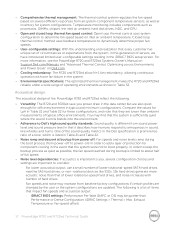
... user or the system configurations are updated. The acoustical design of the PowerEdge R720 and R720xd reflect the following is limited to about half of hard drives. - Exhaust Temperature or Fan speed offset). 37 PowerEdge R720 and R720xd Technical Guide For lower acoustical output, use a small number of lower rotational-speed SATA hard drives, nearline SAS hard drives, or non-rotational devices like whistles and hums. One of the sound quality metrics in the Dell specification...
... user or the system configurations are updated. The acoustical design of the PowerEdge R720 and R720xd reflect the following is limited to about half of hard drives. - Exhaust Temperature or Fan speed offset). 37 PowerEdge R720 and R720xd Technical Guide For lower acoustical output, use a small number of lower rotational-speed SATA hard drives, nearline SAS hard drives, or non-rotational devices like whistles and hums. One of the sound quality metrics in the Dell specification...
Technical Guide
Page 46
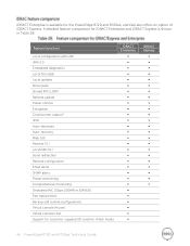
... configuration with USC IPMI 2.0 Embedded diagnostics Local OS install Local updates Driver pack Shared NIC (LOM) Remote update Power control Encryption Crash screen capture1 IPv6 Auto-discovery Auto-recovery Web GUI Remote CLI Local/SSH CLI Serial redirection Remote configuration Email alerts SNMP alerts Power monitoring Comprehensive monitoring Dedicated NIC 1Gbps (100MB in Table 28. iDRAC7 Enterprise is shown in iDRAC6) Part replacement Backup and restore configurations Virtual console (4 user) Virtual console chat Support for customer-supplied SD cards for the PowerEdge R720...
... configuration with USC IPMI 2.0 Embedded diagnostics Local OS install Local updates Driver pack Shared NIC (LOM) Remote update Power control Encryption Crash screen capture1 IPv6 Auto-discovery Auto-recovery Web GUI Remote CLI Local/SSH CLI Serial redirection Remote configuration Email alerts SNMP alerts Power monitoring Comprehensive monitoring Dedicated NIC 1Gbps (100MB in Table 28. iDRAC7 Enterprise is shown in iDRAC6) Part replacement Backup and restore configurations Virtual console (4 user) Virtual console chat Support for customer-supplied SD cards for the PowerEdge R720...
Technical Guide
Page 57
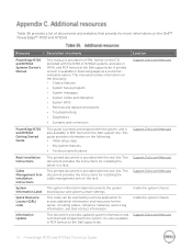
... the rack kits. The document provides the instructions for the server, including videos, reference materials, service tag information, and Dell contact information. This guide provides information on the Dell support site. It is available in PDF format on the following : Chassis features System Setup program System messages System codes and indicators System BIOS Remove and replace procedures Troubleshooting Diagnostics Jumpers and connectors Support.Dell.com/Manuals PowerEdge R720 and...
... the rack kits. The document provides the instructions for the server, including videos, reference materials, service tag information, and Dell contact information. This guide provides information on the Dell support site. It is available in PDF format on the following : Chassis features System Setup program System messages System codes and indicators System BIOS Remove and replace procedures Troubleshooting Diagnostics Jumpers and connectors Support.Dell.com/Manuals PowerEdge R720 and...
Glossary
Page 10
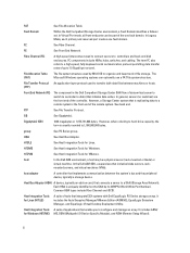
...-speed interconnect used by its WWPN (World Wide Port Number). FAT See File Allocation Table. Fault Domain Within the Dell Compellent Storage Center environment, a Fault Domain identifies a failover set. In Virtual Port mode, all front-end ports can optionally use a FAT file system structure. FTP See File Transfer Protocol. host In the Dell AIM environment, a host may be part of data writes (server to switch to controller to configure and manage an array...
...-speed interconnect used by its WWPN (World Wide Port Number). FAT See File Allocation Table. Fault Domain Within the Dell Compellent Storage Center environment, a Fault Domain identifies a failover set. In Virtual Port mode, all front-end ports can optionally use a FAT file system structure. FTP See File Transfer Protocol. host In the Dell AIM environment, a host may be part of data writes (server to switch to controller to configure and manage an array...
Glossary
Page 16
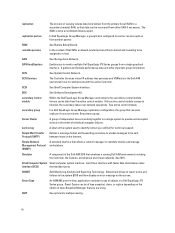
... service in a Dell EqualLogic PS Series group. Simple Network Management Protocol (SNMP) A standard interface that receives replicas of a source volume. Allows hard drives to report errors and failures to function, the secondary takes over network operations. RSW See Remote Setup Wizard. secondary control module Within the Dell EqualLogic Group Manager environment, the secondary control module mirrors cache data from another partner. If the active control module ceases to the system BIOS and then display an error message...
... service in a Dell EqualLogic PS Series group. Simple Network Management Protocol (SNMP) A standard interface that receives replicas of a source volume. Allows hard drives to report errors and failures to function, the secondary takes over network operations. RSW See Remote Setup Wizard. secondary control module Within the Dell EqualLogic Group Manager environment, the secondary control module mirrors cache data from another partner. If the active control module ceases to the system BIOS and then display an error message...
Glossary
Page 18
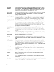
... discover servers and to boot personas and VMRacks on a network hub or switch used to connect to remove a member from a previous replay, for configurations with a template volume. A Dell KACE appliance-based deployment management solution for disk imaging, user state migration, remote site management, system repair and recovery, as well as inventory management, software distribution, reporting, patch management, asset management, scripting, and service desk support through a web-based interface. Synchronous Replication System Control Network (SCN) System Setup...
... discover servers and to boot personas and VMRacks on a network hub or switch used to connect to remove a member from a previous replay, for configurations with a template volume. A Dell KACE appliance-based deployment management solution for disk imaging, user state migration, remote site management, system repair and recovery, as well as inventory management, software distribution, reporting, patch management, asset management, scripting, and service desk support through a web-based interface. Synchronous Replication System Control Network (SCN) System Setup...


