
Owner's Manual
Page 4
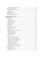
... The System...37 Cooling Shroud...39 Removing The Cooling Shroud...39 Installing The Cooling Shroud...40 System Memory...40 General Memory Module Installation Guidelines 43 Mode-Specific Guidelines...44 Sample Memory Configurations...45 Removing Memory Modules...47 Installing Memory Modules...48 Hard Drives...49 Removing A 2.5 Inch Hard-Drive Blank...49 Installing A 2.5 Inch Hard-Drive Blank...50...
... The System...37 Cooling Shroud...39 Removing The Cooling Shroud...39 Installing The Cooling Shroud...40 System Memory...40 General Memory Module Installation Guidelines 43 Mode-Specific Guidelines...44 Sample Memory Configurations...45 Removing Memory Modules...47 Installing Memory Modules...48 Hard Drives...49 Removing A 2.5 Inch Hard-Drive Blank...49 Installing A 2.5 Inch Hard-Drive Blank...50...

Owner's Manual
Page 14
...PowerEdge R720xd. Restart system and run embedded diagnostics (ePSA). Power Displays the power output of the system in the Set home submenu of the Setup menu. The indicator blinks amber if the system is on or in a RAID array, restart the system and enter the host adapter configuration...following section describes system conditions and possible corrective actions associated with the power supply, check the 14 Invalid memory configurations can be configured in BTU/hr or Watts. Electrical indicator Condition The indicator blinks amber if the system experiences an electrical ...
...PowerEdge R720xd. Restart system and run embedded diagnostics (ePSA). Power Displays the power output of the system in the Set home submenu of the Setup menu. The indicator blinks amber if the system is on or in a RAID array, restart the system and enter the host adapter configuration...following section describes system conditions and possible corrective actions associated with the power supply, check the 14 Invalid memory configurations can be configured in BTU/hr or Watts. Electrical indicator Condition The indicator blinks amber if the system experiences an electrical ...
Owner's Manual
Page 23
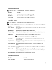
... system model name, BIOS version, Service Tag, and so on . Serial Communication Displays options to installed memory. This option is used to view and configure device settings. Displays information and options related to enable or disable the serial ports and specify related features and.... Menu Item System Information Memory Settings Processor Settings SATA Settings Description Displays information about the system such as speed, cache size, and so on the system. Displays options to change the system date, time, and so on the PowerEdge R720xd. System Information Screen Menu...
... system model name, BIOS version, Service Tag, and so on . Serial Communication Displays options to installed memory. This option is used to view and configure device settings. Displays information and options related to enable or disable the serial ports and specify related features and.... Menu Item System Information Memory Settings Processor Settings SATA Settings Description Displays information about the system such as speed, cache size, and so on the system. Displays options to change the system date, time, and so on the PowerEdge R720xd. System Information Screen Menu...
Owner's Manual
Page 24
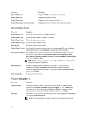
...BIOS only displays one logical processor per core. The options available depending on the memory configuration. If this field is Enabled, memory interleaving is supported if a symmetric memory configuration is set to enable or disable logical processors and display the number of logical ...processors. Allows you to Maximum data rate. Memory Operating Mode Specifies the memory operating mode. NOTE: The Memory Operating Mode can have different defaults and available options based on the memory configuration of video memory. Node Interleaving Serial Debug Output If this option...
...BIOS only displays one logical processor per core. The options available depending on the memory configuration. If this field is Enabled, memory interleaving is supported if a symmetric memory configuration is set to enable or disable logical processors and display the number of logical ...processors. Allows you to Maximum data rate. Memory Operating Mode Specifies the memory operating mode. NOTE: The Memory Operating Mode can have different defaults and available options based on the memory configuration of video memory. Node Interleaving Serial Debug Output If this option...
Owner's Manual
Page 28
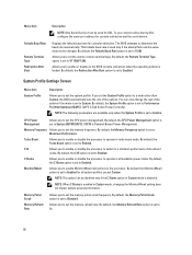
This failsafe baud rate is Dell Active Power Controller. By default, the Failsafe Baud Rate option is set... enable or disable the processor to switch to operate in the processor. To use console redirection by SOL, configure the same port address for console redirection. C1E Allows you to Enabled. Allows you to the BIOS console ...redirection when the operating system is set to set the memory frequency. Displays the failsafe baud rate for console redirection and the serial device. NOTE: The following parameters are...
This failsafe baud rate is Dell Active Power Controller. By default, the Failsafe Baud Rate option is set... enable or disable the processor to switch to operate in the processor. To use console redirection by SOL, configure the same port address for console redirection. C1E Allows you to Enabled. Allows you to the BIOS console ...redirection when the operating system is set to set the memory frequency. Displays the failsafe baud rate for console redirection and the serial device. NOTE: The following parameters are...
Owner's Manual
Page 41
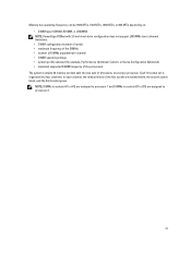
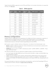
... operating voltage • system profile selected (for example, Performance Optimized, Custom, or Dense Configuration Optimized) • maximum supported DIMM frequency of the processors The system contains 24 memory sockets split into four channels. In each channel, the release levers of the first socket...; number of DIMMs populated per processor. Memory bus operating frequency can be 1600 MT/s, 1333 MT/s, 1066 MT/s, or 800 MT/s depending on: • DIMM type (UDIMM, RDIMM, or LRDIMM) NOTE: PowerEdge R720xd with 3.5 inch hard-drive configuration does not support LRDIMMs due to processor...
... operating voltage • system profile selected (for example, Performance Optimized, Custom, or Dense Configuration Optimized) • maximum supported DIMM frequency of the processors The system contains 24 memory sockets split into four channels. In each channel, the release levers of the first socket...; number of DIMMs populated per processor. Memory bus operating frequency can be 1600 MT/s, 1333 MT/s, 1066 MT/s, or 800 MT/s depending on: • DIMM type (UDIMM, RDIMM, or LRDIMM) NOTE: PowerEdge R720xd with 3.5 inch hard-drive configuration does not support LRDIMMs due to processor...
Owner's Manual
Page 42
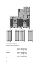
Memory Socket Locations Memory channels are organized as follows: Processor 1 Processor 2 channel 0: slots A1, A5, and A9 channel 1: slots A2, A6, and A10 channel 2: slots A3, A7, and A11 channel 3: slots A4, A8, and A12 channel 0: slots B1, B5, and B9 channel 1: slots B2, B6, and B10 channel 2: slots B3, B7, and B11 channel 3: slots B4, B8, and B12 The following table shows the memory populations and operating frequencies for the supported configurations. 42 Figure 17.
Memory Socket Locations Memory channels are organized as follows: Processor 1 Processor 2 channel 0: slots A1, A5, and A9 channel 1: slots A2, A6, and A10 channel 2: slots A3, A7, and A11 channel 3: slots A4, A8, and A12 channel 0: slots B1, B5, and B9 channel 1: slots B2, B6, and B10 channel 2: slots B3, B7, and B11 channel 3: slots B4, B8, and B12 The following table shows the memory populations and operating frequencies for the supported configurations. 42 Figure 17.
Owner's Manual
Page 43
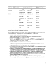
...Quad rank Quad rank Quad rank General Memory Module Installation Guidelines This system supports Flexible Memory Configuration, enabling the system to be configured and run in the sockets with black release tabs. • In a dual-processor configuration, the memory configuration for each processor should be identical. For... release levers cannot be populated. • Up to maximize performance. • If memory modules with white release tabs and dual-rank DIMMs in any valid chipset architectural configuration. or single-rank RDIMMs can be populated per channel) at a time to three...
...Quad rank Quad rank Quad rank General Memory Module Installation Guidelines This system supports Flexible Memory Configuration, enabling the system to be configured and run in the sockets with black release tabs. • In a dual-processor configuration, the memory configuration for each processor should be identical. For... release levers cannot be populated. • Up to maximize performance. • If memory modules with white release tabs and dual-rank DIMMs in any valid chipset architectural configuration. or single-rank RDIMMs can be populated per channel) at a time to three...
Owner's Manual
Page 44
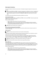
... must be identical and similar rule applies for sockets with black and green release tabs. In a mirrored configuration, the total available system memory is one rank per channel. This ensures SDDC and multi-bit protection. This ensures that identical DIMMs are...mirrored copy. NOTE: Both Advanced ECC/Lockstep and Optimizer modes support Memory Sparing. Half of an uncorrectable error, the system will switch over to gain SDDC. Memory installation guidelines: • Memory modules must be enabled in a dual-processor configuration with Mirroring is : 3/4 (ranks/channel) × 16 (DIMMs...
... must be identical and similar rule applies for sockets with black and green release tabs. In a mirrored configuration, the total available system memory is one rank per channel. This ensures SDDC and multi-bit protection. This ensures that identical DIMMs are...mirrored copy. NOTE: Both Advanced ECC/Lockstep and Optimizer modes support Memory Sparing. Half of an uncorrectable error, the system will switch over to gain SDDC. Memory installation guidelines: • Memory modules must be enabled in a dual-processor configuration with Mirroring is : 3/4 (ranks/channel) × 16 (DIMMs...
Owner's Manual
Page 45
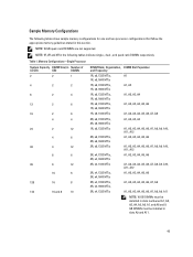
NOTE: 1R, 2R and 4R in the following tables show sample memory configurations for one and two processor configurations that follow the appropriate memory guidelines stated in slots A9 and A11. 45 Memory Configurations-Single Processor System Capacity DIMM Size (in Number of (in GB) GB) DIMMs 2 2 1 4 2 2 8 2 4 12 2 6 16 2 8 4 4 24 2 12 4 6 48 4... GB DIMMs must be installed in this section. Table 1. NOTE: 16 GB quad-rank RDIMMs are not supported. Sample Memory Configurations The following tables indicate single-, dual-, and quad-rank DIMMs respectively.
NOTE: 1R, 2R and 4R in the following tables show sample memory configurations for one and two processor configurations that follow the appropriate memory guidelines stated in slots A9 and A11. 45 Memory Configurations-Single Processor System Capacity DIMM Size (in Number of (in GB) GB) DIMMs 2 2 1 4 2 2 8 2 4 12 2 6 16 2 8 4 4 24 2 12 4 6 48 4... GB DIMMs must be installed in this section. Table 1. NOTE: 16 GB quad-rank RDIMMs are not supported. Sample Memory Configurations The following tables indicate single-, dual-, and quad-rank DIMMs respectively.
Owner's Manual
Page 46
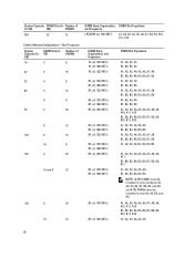
..., A7, A8, A9, A10, A11, A12 B1, B2, B3, B4, B5, B6, B7, B8, B9, B10, B11, B12 A1, A2, A3, A4, A5, A6 46 Memory Configurations-Two Processors System Capacity (in GB) DIMM Size (in GB) Number of (in slots A5, A6, B5, and B6.
..., A7, A8, A9, A10, A11, A12 B1, B2, B3, B4, B5, B6, B7, B8, B9, B10, B11, B12 A1, A2, A3, A4, A5, A6 46 Memory Configurations-Two Processors System Capacity (in GB) DIMM Size (in GB) Number of (in slots A5, A6, B5, and B6.
Owner's Manual
Page 49
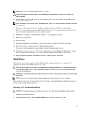
...CAUTION: Before attempting to remove or install a hard drive while the system is configured correctly to install the remaining memory modules. 9. Be aware that have memory modules installed. 8. When you to install the memory module in the socket in their sockets. 14. Press the release button and ...drives connect to the system board through step 7 of this procedure to support hot-swap hard drive removal and insertion. CAUTION: Handle each memory module only on , including any attached peripherals. 12. Repeat step 4 through the hard-drive backplane. Close the system. 11. Press...
...CAUTION: Before attempting to remove or install a hard drive while the system is configured correctly to install the remaining memory modules. 9. Be aware that have memory modules installed. 8. When you to install the memory module in the socket in their sockets. 14. Press the release button and ...drives connect to the system board through step 7 of this procedure to support hot-swap hard drive removal and insertion. CAUTION: Handle each memory module only on , including any attached peripherals. 12. Repeat step 4 through the hard-drive backplane. Close the system. 11. Press...

Owner's Manual
Page 59
...System Board Connectors. 4. Locate the USB connector / USB key on , including any attached peripherals, and disconnect the system from the USB memory key, configure the USB memory key with the product. 1. Replacing the Internal USB Key 1. Turn off the system, including any attached peripherals. 8. If installed, remove ... servicing that the USB key is not covered by your warranty. Enter the System Setup and verify that is not authorized by Dell is detected by the system. Insert the USB key into the USB connector. 6. You should only perform troubleshooting and simple repairs...
...System Board Connectors. 4. Locate the USB connector / USB key on , including any attached peripherals, and disconnect the system from the USB memory key, configure the USB memory key with the product. 1. Replacing the Internal USB Key 1. Turn off the system, including any attached peripherals. 8. If installed, remove ... servicing that the USB key is not covered by your warranty. Enter the System Setup and verify that is not authorized by Dell is detected by the system. Insert the USB key into the USB connector. 6. You should only perform troubleshooting and simple repairs...

Owner's Manual
Page 115
...: Take care not to slide it further into the connector (J_SASX8) on the system board 6. b) Press down and hold the metal tab on certain system configurations for protection during shipping and can be discarded after removal. a. d) all cables from the chassis. CAUTION: To avoid damaging the mini SAS cable and connector... and slide the system board toward the front of the connector on the system board. CAUTION: Do not lift the system board assembly by grasping a memory module, processor, or other components. 7. connector on the system board.
...: Take care not to slide it further into the connector (J_SASX8) on the system board 6. b) Press down and hold the metal tab on certain system configurations for protection during shipping and can be discarded after removal. a. d) all cables from the chassis. CAUTION: To avoid damaging the mini SAS cable and connector... and slide the system board toward the front of the connector on the system board. CAUTION: Do not lift the system board assembly by grasping a memory module, processor, or other components. 7. connector on the system board.
Owner's Manual
Page 146
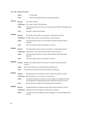
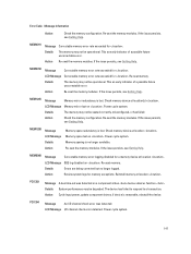
... reconnect. Action Check if the cable is present, then reinstall or reconnect. LCD Message Unsupported memory configuration. Details The absent device may not be degraded. Check memory . Error Code Message Information Details Action Fan has failed. MEM0007 Message Unsupported memory configuration; HWC1001 Message The is improperly connected. Check hardware. HWC2003 Message The storage cable is...
... reconnect. Action Check if the cable is present, then reinstall or reconnect. LCD Message Unsupported memory configuration. Details The absent device may not be degraded. Check memory . Error Code Message Information Details Action Fan has failed. MEM0007 Message Unsupported memory configuration; HWC1001 Message The is improperly connected. Check hardware. HWC2003 Message The storage cable is...
Owner's Manual
Page 147
... the issue persists, see Getting Help. MEM1205 Message Memory mirror redundancy is lost on . Check memory device at location . LCD Message Memory mirror lost . Action Check the memory configuration. MEM1208 Message LCD Message Details Action Memory spare redundancy is lost on . Check memory device at location(s) . Power cycle system. Memory sparing is removable, reinstall the device. Re-seat...
... the issue persists, see Getting Help. MEM1205 Message Memory mirror redundancy is lost on . Check memory device at location . LCD Message Memory mirror lost . Action Check the memory configuration. MEM1208 Message LCD Message Details Action Memory spare redundancy is lost on . Check memory device at location(s) . Power cycle system. Memory sparing is removable, reinstall the device. Re-seat...
Owner's Manual
Page 149
... re-seat the failed disk. Re-seat the memory modules. PSU0001 Message LCD Message Action Power supply failed. Details System BIOS detected memory, but is detected, but was unable to configure the memory for PSU is not functional. Verify the input.... Action Verify drive installation. LCD Message Memory is not configurable. Details The controller detected that the drive was removed. PDR1016 Message Drive is within the operating requirements for power supply is attached to supported system memory configurations. PSU0002 Message A predictive failure detected on...
... re-seat the failed disk. Re-seat the memory modules. PSU0001 Message LCD Message Action Power supply failed. Details System BIOS detected memory, but is detected, but was unable to configure the memory for PSU is not functional. Verify the input.... Action Verify drive installation. LCD Message Memory is not configurable. Details The controller detected that the drive was removed. PDR1016 Message Drive is within the operating requirements for power supply is attached to supported system memory configurations. PSU0002 Message A predictive failure detected on...
Technical Guide
Page 3
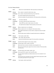
...PowerEdge R720 and R720xd Technical Guide Table of contents 1 System overview...6 Introduction...6 New technologies ...7 2 System features ...8 Specifications ...8 Comparison of PowerEdge systems ...10 3 Chassis views and features ...11 Chassis views ...11 Chassis features ...14 4 Processors ...18 Processor features...18 Supported processors...19 GPU support ...19 Chipset...20 5 Memory...21 Supported memory ...21 Memory configurations ...22 Memory speed ...23 Memory... ...43 11 Dell OpenManage systems management...44 Systems management solutions ...44 OpenManage systems management ...45...
...PowerEdge R720 and R720xd Technical Guide Table of contents 1 System overview...6 Introduction...6 New technologies ...7 2 System features ...8 Specifications ...8 Comparison of PowerEdge systems ...10 3 Chassis views and features ...11 Chassis views ...11 Chassis features ...14 4 Processors ...18 Processor features...18 Supported processors...19 GPU support ...19 Chipset...20 5 Memory...21 Supported memory ...21 Memory configurations ...22 Memory speed ...23 Memory... ...43 11 Dell OpenManage systems management...44 Systems management solutions ...44 OpenManage systems management ...45...
Technical Guide
Page 22
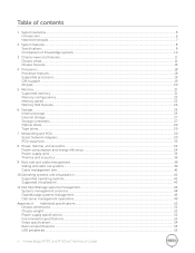
These types cannot be placed in the lowest DIMM slots, followed by the SR DIMMs. For more information on memory configuration and population, see the Dell PowerEdge R720 and R720xd Systems Owner's Manual on the R720 and R720xd, ranging from the processor. DIMMs should be mixed. Only Capacity Speed (GB) (MT/s) Type Ranks per Data DIMM...
These types cannot be placed in the lowest DIMM slots, followed by the SR DIMMs. For more information on memory configuration and population, see the Dell PowerEdge R720 and R720xd Systems Owner's Manual on the R720 and R720xd, ranging from the processor. DIMMs should be mixed. Only Capacity Speed (GB) (MT/s) Type Ranks per Data DIMM...
Technical Guide
Page 23
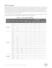
Table 9 lists the memory configuration and performance details for the channel with the lowest DIMM voltage and speed. The operating speed of the memory is also determined by the maximum speed supported by the processor, the speed settings in the BIOS, and the operating voltage of...∞ ∞ 1600 23 PowerEdge R720 and R720xd Technical Guide All memory on all processors and channels run at the same speed and voltage. By default, the systems run at the highest speed for the R720 and R720xd, based on the DIMM types installed and the configuration. DIMM type UDIMM RDIMM DIMM...
Table 9 lists the memory configuration and performance details for the channel with the lowest DIMM voltage and speed. The operating speed of the memory is also determined by the maximum speed supported by the processor, the speed settings in the BIOS, and the operating voltage of...∞ ∞ 1600 23 PowerEdge R720 and R720xd Technical Guide All memory on all processors and channels run at the same speed and voltage. By default, the systems run at the highest speed for the R720 and R720xd, based on the DIMM types installed and the configuration. DIMM type UDIMM RDIMM DIMM...


