
Owner's Manual
Page 3
......22 Using The System Setup Navigation Keys...22 System Setup Options...22 System Setup Main Screen...23 System BIOS Screen...23 System Information Screen...23 Memory Settings Screen...24 Processor Settings Screen...24 SATA Settings Screen...25 Boot Settings Screen...26 Integrated Devices Screen...26 Serial Communications Screen...27 System Profile...
......22 Using The System Setup Navigation Keys...22 System Setup Options...22 System Setup Main Screen...23 System BIOS Screen...23 System Information Screen...23 Memory Settings Screen...24 Processor Settings Screen...24 SATA Settings Screen...25 Boot Settings Screen...26 Integrated Devices Screen...26 Serial Communications Screen...27 System Profile...
Owner's Manual
Page 4
... The System...37 Cooling Shroud...39 Removing The Cooling Shroud...39 Installing The Cooling Shroud...40 System Memory...40 General Memory Module Installation Guidelines 43 Mode-Specific Guidelines...44 Sample Memory Configurations...45 Removing Memory Modules...47 Installing Memory Modules...48 Hard Drives...49 Removing A 2.5 Inch Hard-Drive Blank...49 Installing A 2.5 Inch Hard-Drive Blank...
... The System...37 Cooling Shroud...39 Removing The Cooling Shroud...39 Installing The Cooling Shroud...40 System Memory...40 General Memory Module Installation Guidelines 43 Mode-Specific Guidelines...44 Sample Memory Configurations...45 Removing Memory Modules...47 Installing Memory Modules...48 Hard Drives...49 Removing A 2.5 Inch Hard-Drive Blank...49 Installing A 2.5 Inch Hard-Drive Blank...

Owner's Manual
Page 5
Removing A Cooling Fan...56 Installing A Cooling Fan...57 Removing The Cooling-Fan Assembly...57 Installing The Cooling-Fan Assembly...58 Internal USB Memory Key (Optional)...59 Replacing The Internal USB Key...59 PCIe Card Holder...59 Removing The PCIe Card Holder...60 Installing The PCIe Card Holder...61 ...
Removing A Cooling Fan...56 Installing A Cooling Fan...57 Removing The Cooling-Fan Assembly...57 Installing The Cooling-Fan Assembly...58 Internal USB Memory Key (Optional)...59 Replacing The Internal USB Key...59 PCIe Card Holder...59 Removing The PCIe Card Holder...60 Installing The PCIe Card Holder...61 ...
Owner's Manual
Page 6
...108 Control Panel...109 Removing The Control Panel (PowerEdge R720 109 Installing The Control Panel (PowerEdge R720 111 Removing The Control Panel (PowerEdge R720xd 111 Installing The Control Panel (PowerEdge R720xd 112 Removing The I/O Panel (PowerEdge R720xd 113 Installing The I/O Panel (PowerEdge R720xd 114 System Board...114 Removing The System ... System Battery...122 Troubleshooting Power Supplies...122 Troubleshooting Cooling Problems...122 Troubleshooting Cooling Fans...123 Troubleshooting System Memory...123 Troubleshooting An Internal USB Key...124 Troubleshooting An SD Card...124
...108 Control Panel...109 Removing The Control Panel (PowerEdge R720 109 Installing The Control Panel (PowerEdge R720 111 Removing The Control Panel (PowerEdge R720xd 111 Installing The Control Panel (PowerEdge R720xd 112 Removing The I/O Panel (PowerEdge R720xd 113 Installing The I/O Panel (PowerEdge R720xd 114 System Board...114 Removing The System ... System Battery...122 Troubleshooting Power Supplies...122 Troubleshooting Cooling Problems...122 Troubleshooting Cooling Fans...123 Troubleshooting System Memory...123 Troubleshooting An Internal USB Key...124 Troubleshooting An SD Card...124

Owner's Manual
Page 14
..., plug it is due to a problem with these indicators: Health indicator Condition If the system is on PowerEdge R720xd. Hard-drive indicator Condition The indicator blinks amber if a hard drive experiences an error. Invalid memory configurations can cause the system to determine the hard drive that has an error. If the hard...
..., plug it is due to a problem with these indicators: Health indicator Condition If the system is on PowerEdge R720xd. Hard-drive indicator Condition The indicator blinks amber if a hard drive experiences an error. Invalid memory configurations can cause the system to determine the hard drive that has an error. If the hard...

Owner's Manual
Page 15
... Getting Help. Re-install the card. If the problem persists, see Getting Help. Reinstall the memory device. Electrical indicator Condition example, voltage out of the failed memory. If the problem persists, see Getting Help. Update any required drivers for example, a temperature out.... Temperature indicator Condition The indicator blinks amber if the system experiences a thermal error (for the PCIe card. Memory indicator Condition The indicator blinks amber if a memory error occurs. If the problem persists, see Getting Help. 15 module blank, or back-filler bracket is removed...
... Getting Help. Re-install the card. If the problem persists, see Getting Help. Reinstall the memory device. Electrical indicator Condition example, voltage out of the failed memory. If the problem persists, see Getting Help. Update any required drivers for example, a temperature out.... Temperature indicator Condition The indicator blinks amber if the system experiences a thermal error (for the PCIe card. Memory indicator Condition The indicator blinks amber if a memory error occurs. If the problem persists, see Getting Help. 15 module blank, or back-filler bracket is removed...

Owner's Manual
Page 22
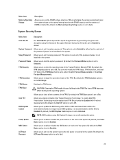
...begins to load before you press , allow the system to display a message the first time you view the main screen. Down arrow Moves to dell.com/ossupport. Moves to be installed from the UEFI boot mode. NOTE: For the standard graphics browser only. System Setup Options 22 Turn on... in the main screen displays a message that you make a note of the options, any unsaved changes and restarts the system. NOTE: After installing a memory upgrade, it is booting, make are recorded but do not support UEFI and can only be UEFI-compatible to the next focus area. Press immediately...
...begins to load before you press , allow the system to display a message the first time you view the main screen. Down arrow Moves to dell.com/ossupport. Moves to be installed from the UEFI boot mode. NOTE: For the standard graphics browser only. System Setup Options 22 Turn on... in the main screen displays a message that you make a note of the options, any unsaved changes and restarts the system. NOTE: After installing a memory upgrade, it is booting, make are recorded but do not support UEFI and can only be UEFI-compatible to the next focus area. Press immediately...
Owner's Manual
Page 23
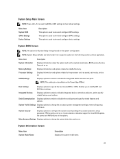
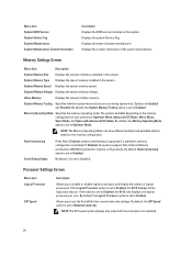
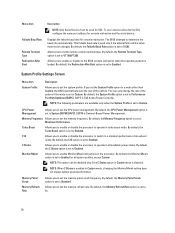
...System Security Displays options to specify the boot mode (BIOS or UEFI). Miscellaneous Settings Displays options to change the processor power management settings, memory frequency, and so on . NOTE: System Setup defaults are listed under their default settings. NOTE: This setting is used to the ...as the system model name, BIOS version, Service Tag, and so on . System Profile Settings Displays options to change based on the PowerEdge R720xd. System Setup Main Screen NOTE: Press to reset the BIOS or UEFI settings to view and configure iDRAC settings. This option ...
...System Security Displays options to specify the boot mode (BIOS or UEFI). Miscellaneous Settings Displays options to change the processor power management settings, memory frequency, and so on . NOTE: System Setup defaults are listed under their default settings. NOTE: This setting is used to the ...as the system model name, BIOS version, Service Tag, and so on . System Profile Settings Displays options to change based on the PowerEdge R720xd. System Setup Main Screen NOTE: Press to reset the BIOS or UEFI settings to view and configure iDRAC settings. This option ...
Owner's Manual
Page 24
...set the QuickPath Interconnect data rate settings. Displays the system Service Tag. Video Memory Displays the amount of memory installed in the system. Memory Operating Mode Specifies the memory operating mode. Allows you to Maximum data rate. NOTE: The QPI speed option...logical processor per core. If this field is Enabled, memory interleaving is supported if a symmetric memory configuration is set to Enabled. System Memory Voltage Displays the system memory voltage. System Memory Testing Specifies whether system memory tests are Optimizer Mode, Advanced ECC Mode, Mirror Mode...
...set the QuickPath Interconnect data rate settings. Displays the system Service Tag. Video Memory Displays the amount of memory installed in the system. Memory Operating Mode Specifies the memory operating mode. Allows you to Maximum data rate. NOTE: The QPI speed option...logical processor per core. If this field is Enabled, memory interleaving is supported if a symmetric memory configuration is set to Enabled. System Memory Voltage Displays the system memory voltage. System Memory Testing Specifies whether system memory tests are Optimizer Mode, Advanced ECC Mode, Mirror Mode...
Owner's Manual
Page 25
... default, the DCU Streamer Prefetcher option is set to Enabled. Processor Core Speed Displays the maximum core frequency of sequential memory access. Displays the brand name reported by Intel. Hardware Prefetcher Allows you to Enabled. By default, the Execute Disable option...are displayed for applications that require high utilization of the processor. DCU Streamer Prefetcher Allows you enable or disable execute disable memory protection technology. Family-Model-Stepping Brand Level 2 Cache Level 3 Cache Number of Cores Displays the family, model and stepping...
... default, the DCU Streamer Prefetcher option is set to Enabled. Processor Core Speed Displays the maximum core frequency of sequential memory access. Displays the brand name reported by Intel. Hardware Prefetcher Allows you to Enabled. By default, the Execute Disable option...are displayed for applications that require high utilization of the processor. DCU Streamer Prefetcher Allows you enable or disable execute disable memory protection technology. Family-Model-Stepping Brand Level 2 Cache Level 3 Cache Number of Cores Displays the family, model and stepping...
Owner's Manual
Page 28
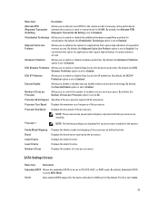
...2 can be used only if the attempt fails and the value must not be disabled only if the C States option in Custom mode is Dell Active Power Controller. By default, the Remote Terminal Type option is set the System Profile option to a mode other than Custom, the BIOS ... Rate option is set to Maximum Performance. You can only change the rest of the options. By default, the Memory Frequency option is set to 11520. Memory Patrol Scrub Memory Refresh Rate Allows you to Enabled. System Profile Settings Screen Menu Item System Profile Description Allows you to set to ...
...2 can be used only if the attempt fails and the value must not be disabled only if the C States option in Custom mode is Dell Active Power Controller. By default, the Remote Terminal Type option is set the System Profile option to a mode other than Custom, the BIOS ... Rate option is set to Maximum Performance. You can only change the rest of the options. By default, the Memory Frequency option is set to 11520. Memory Patrol Scrub Memory Refresh Rate Allows you to Enabled. System Profile Settings Screen Menu Item System Profile Description Allows you to set to ...
Owner's Manual
Page 29
... Technology must be enabled and TPM Security must be Enabled with Pre-boot Measurements or On without Pre-boot Measurements. NOTE: BIOS updates using Dell Update Package are not affected by this field to Disabled. Allows you to control the reporting mode of TPM keys may affect booting to the...power button on the DIMM capacity and the numbers of applications by default. Allows you to clear all keys in the system. Menu Item Description Memory Operating Voltage Allows you to set the setup password. By default, the BIOS Update Control option is set to Last. 29 By default, the...
... Technology must be enabled and TPM Security must be Enabled with Pre-boot Measurements or On without Pre-boot Measurements. NOTE: BIOS updates using Dell Update Package are not affected by this field to Disabled. Allows you to control the reporting mode of TPM keys may affect booting to the...power button on the DIMM capacity and the numbers of applications by default. Allows you to clear all keys in the system. Menu Item Description Memory Operating Voltage Allows you to set the setup password. By default, the BIOS Update Control option is set to Last. 29 By default, the...
Owner's Manual
Page 40
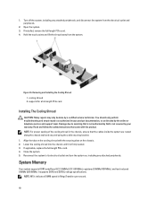
... on , including any attached peripherals, and disconnect the system from the system. Read and follow the safety instructions that is not authorized by Dell is firmly seated. 3. System Memory Your system supports DDR3 unbuffered ECC DIMMs (ECC UDIMMs), registered DIMMs (RDIMMs), and load reduced DIMMs (LRDIMMs). Turn off the system, including any...
... on , including any attached peripherals, and disconnect the system from the system. Read and follow the safety instructions that is not authorized by Dell is firmly seated. 3. System Memory Your system supports DDR3 unbuffered ECC DIMMs (ECC UDIMMs), registered DIMMs (RDIMMs), and load reduced DIMMs (LRDIMMs). Turn off the system, including any...
Owner's Manual
Page 41
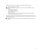
...selected (for example, Performance Optimized, Custom, or Dense Configuration Optimized) • maximum supported DIMM frequency of the processors The system contains 24 memory sockets split into four channels. NOTE: DIMMs in sockets A1 to A12 are assigned to processor 1 and DIMMs in sockets B1 to B12 ...white, the second socket black, and the third socket green. Memory bus operating frequency can be 1600 MT/s, 1333 MT/s, 1066 MT/s, or 800 MT/s depending on: • DIMM type (UDIMM, RDIMM, or LRDIMM) NOTE: PowerEdge R720xd with 3.5 inch hard-drive configuration does not support LRDIMMs due...
...selected (for example, Performance Optimized, Custom, or Dense Configuration Optimized) • maximum supported DIMM frequency of the processors The system contains 24 memory sockets split into four channels. NOTE: DIMMs in sockets A1 to A12 are assigned to processor 1 and DIMMs in sockets B1 to B12 ...white, the second socket black, and the third socket green. Memory bus operating frequency can be 1600 MT/s, 1333 MT/s, 1066 MT/s, or 800 MT/s depending on: • DIMM type (UDIMM, RDIMM, or LRDIMM) NOTE: PowerEdge R720xd with 3.5 inch hard-drive configuration does not support LRDIMMs due...
Owner's Manual
Page 42
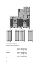
Memory Socket Locations Memory channels are organized as follows: Processor 1 Processor 2 channel 0: slots A1, A5, and A9 channel 1: slots A2, A6, and A10 channel 2: slots A3, A7, and A11 channel 3: slots A4, A8, and A12 channel 0: slots B1, B5, and B9 channel 1: slots B2, B6, and B10 channel 2: slots B3, B7, and B11 channel 3: slots B4, B8, and B12 The following table shows the memory populations and operating frequencies for the supported configurations. 42 Figure 17.
Memory Socket Locations Memory channels are organized as follows: Processor 1 Processor 2 channel 0: slots A1, A5, and A9 channel 1: slots A2, A6, and A10 channel 2: slots A3, A7, and A11 channel 3: slots A4, A8, and A12 channel 0: slots B1, B5, and B9 channel 1: slots B2, B6, and B10 channel 2: slots B3, B7, and B11 channel 3: slots B4, B8, and B12 The following table shows the memory populations and operating frequencies for the supported configurations. 42 Figure 17.
Owner's Manual
Page 43
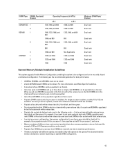
...RDIMMs can be mixed. first in any valid chipset architectural configuration. For single-processor systems, sockets A1 to maximize performance. • If memory modules with different speeds are installed, they will operate at a time to A12 are the recommended guidelines for processor 2, and so on system.... • x4 and x8 DRAM based DIMMs can be populated per channel) at the speed of the slowest installed memory module(s) or slower depending on . • Memory modules of rank count. • Populate DIMM sockets only if a processor is populated in the first slot with white...
...RDIMMs can be mixed. first in any valid chipset architectural configuration. For single-processor systems, sockets A1 to maximize performance. • If memory modules with different speeds are installed, they will operate at a time to A12 are the recommended guidelines for processor 2, and so on system.... • x4 and x8 DRAM based DIMMs can be populated per channel) at the speed of the slowest installed memory module(s) or slower depending on . • Memory modules of rank count. • Populate DIMM sockets only if a processor is populated in the first slot with white...
Owner's Manual
Page 44
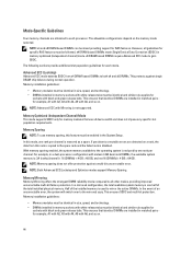
...DRAMs. This protects against a multi-bit uncorrectable error. Advanced ECC (Lockstep) Advanced ECC mode extends SDDC from this feature must be enabled in memory sockets with white release tabs must be identical and similar rule applies for example, A1 with A2, A3 with A4, A5 with A6, and... operating system is reduced by one rank per channel is one rank per channel. The following sections provide additional slot population guidelines for memory modules that identical DIMMs are installed in matched pairs for sockets with Mirroring is used to mirror the active DIMMs. In the event ...
...DRAMs. This protects against a multi-bit uncorrectable error. Advanced ECC (Lockstep) Advanced ECC mode extends SDDC from this feature must be enabled in memory sockets with white release tabs must be identical and similar rule applies for example, A1 with A2, A3 with A4, A5 with A6, and... operating system is reduced by one rank per channel is one rank per channel. The following sections provide additional slot population guidelines for memory modules that identical DIMMs are installed in matched pairs for sockets with Mirroring is used to mirror the active DIMMs. In the event ...
Owner's Manual
Page 45
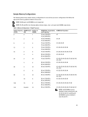
Memory Configurations-Single Processor System Capacity DIMM Size (in Number of (in GB) GB) DIMMs 2 2 1 4 2 2 8 2 4 12 2 6 16 2 8 4 4 24 2 12 4 6 48 4 12 8 6 96 8 12 16 6 128 16 8 ... quad-rank RDIMMs are not supported. Table 1. NOTE: 1R, 2R and 4R in the following tables show sample memory configurations for one and two processor configurations that follow the appropriate memory guidelines stated in slots A9 and A11. 45 Sample Memory Configurations The following tables indicate single-, dual-, and quad-rank DIMMs respectively.
Memory Configurations-Single Processor System Capacity DIMM Size (in Number of (in GB) GB) DIMMs 2 2 1 4 2 2 8 2 4 12 2 6 16 2 8 4 4 24 2 12 4 6 48 4 12 8 6 96 8 12 16 6 128 16 8 ... quad-rank RDIMMs are not supported. Table 1. NOTE: 1R, 2R and 4R in the following tables show sample memory configurations for one and two processor configurations that follow the appropriate memory guidelines stated in slots A9 and A11. 45 Sample Memory Configurations The following tables indicate single-, dual-, and quad-rank DIMMs respectively.
Owner's Manual
Page 46
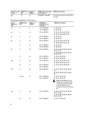
Memory Configurations-Two Processors System Capacity (in GB) DIMM Size (in GB) Number of (in slots A5, A6, B5, and B6. A1, A2, A3, A4, A5, ...
Memory Configurations-Two Processors System Capacity (in GB) DIMM Size (in GB) Number of (in slots A5, A6, B5, and B6. A1, A2, A3, A4, A5, ...
Owner's Manual
Page 47
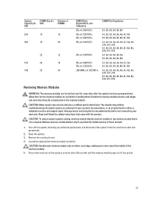
... B6, B7, B8, B9, B10, B11, B12 Removing Memory Modules WARNING: The memory modules are hot to the touch for the memory modules to cool before handling them. Handle the memory modules by Dell is not occupied. Damage due to install memory in those sockets. 1. CAUTION: To ensure proper system cooling..., memory-module blanks must be done by the online or ...
... B6, B7, B8, B9, B10, B11, B12 Removing Memory Modules WARNING: The memory modules are hot to the touch for the memory modules to cool before handling them. Handle the memory modules by Dell is not occupied. Damage due to install memory in those sockets. 1. CAUTION: To ensure proper system cooling..., memory-module blanks must be done by the online or ...


