
Owner's Manual
Page 9
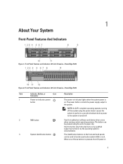
Front-Panel Features and Indicators (2.5 Inch Chassis)-PowerEdge R720 Item Indicator, Button, or Icon Description Connector 1 Power-on indicator, power button The power-on indicator lights when the system power is on the front ... button controls the power supply output to do so by qualified support personnel or by the operating system's documentation. Front-Panel Features and Indicators (3.5 Inch Chassis)-PowerEdge R720 Figure 2.
Front-Panel Features and Indicators (2.5 Inch Chassis)-PowerEdge R720 Item Indicator, Button, or Icon Description Connector 1 Power-on indicator, power button The power-on indicator lights when the system power is on the front ... button controls the power supply output to do so by qualified support personnel or by the operating system's documentation. Front-Panel Features and Indicators (3.5 Inch Chassis)-PowerEdge R720 Figure 2.
Owner's Manual
Page 11
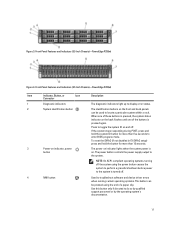
...indicator lights when the system power is pressed again. Use this button only if directed to the system. Figure 3. Front-Panel Features and Indicators (2.5 Inch Chassis)-PowerEdge R720xd Item Indicator, Button, or Icon Description Connector 1 Diagnostic indicators The diagnostic indicators light up to display error status. 2 System identification button The identification ... the power supply output to do so by qualified support personnel or by the operating system's documentation. 11 Front-Panel Features and Indicators (3.5 Inch Chassis)-PowerEdge R720xd Figure 4.
...indicator lights when the system power is pressed again. Use this button only if directed to the system. Figure 3. Front-Panel Features and Indicators (2.5 Inch Chassis)-PowerEdge R720xd Item Indicator, Button, or Icon Description Connector 1 Diagnostic indicators The diagnostic indicators light up to display error status. 2 System identification button The identification ... the power supply output to do so by qualified support personnel or by the operating system's documentation. 11 Front-Panel Features and Indicators (3.5 Inch Chassis)-PowerEdge R720xd Figure 4.

Owner's Manual
Page 36
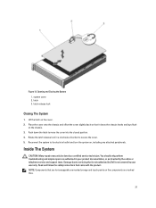
... the system cover when the system is on components in your warranty. You should only perform troubleshooting and simple repairs as directed by Dell is recommended that came with the keylock. Opening The System NOTE: It is not covered by your product documentation, or as authorized ... Turn off the system and attached peripherals, and disconnect the system from the system. 36 Grasp the cover on top of the bezel onto the chassis. 2. keylock 3. CAUTION: Do not operate the system without the cover for a duration exceeding five minutes. Lift the latch on both sides, ...
... the system cover when the system is on components in your warranty. You should only perform troubleshooting and simple repairs as directed by Dell is recommended that came with the keylock. Opening The System NOTE: It is not covered by your product documentation, or as authorized ... Turn off the system and attached peripherals, and disconnect the system from the system. 36 Grasp the cover on top of the bezel onto the chassis. 2. keylock 3. CAUTION: Do not operate the system without the cover for a duration exceeding five minutes. Lift the latch on both sides, ...
Owner's Manual
Page 37
... the latch on the components are marked blue. 37 Place the cover onto the chassis and offset the cover slightly back so that came with the product. NOTE: Components that is not authorized by Dell is not covered by your product documentation, or as authorized in a clockwise direction ...to its electrical outlet and turn the system on the chassis. 3. Rotate the latch release lock in your warranty. Reconnect the ...
... the latch on the components are marked blue. 37 Place the cover onto the chassis and offset the cover slightly back so that came with the product. NOTE: Components that is not authorized by Dell is not covered by your product documentation, or as authorized in a clockwise direction ...to its electrical outlet and turn the system on the chassis. 3. Rotate the latch release lock in your warranty. Reconnect the ...
Owner's Manual
Page 40
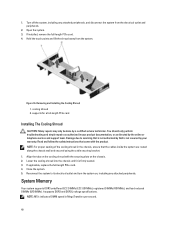
.../s indicates DIMM speed in the chassis, ensure that is not authorized by the online or telephone service and support team. Open the system. 3. Removing and Installing the Cooling Shroud 1. You should only perform troubleshooting and simple repairs as directed by Dell is firmly seated. 3. If ...applicable, replace the full-length PCIe card. 4. Close the system. 5. Lower the cooling shroud into the chassis until it is not covered by a certified service technician. Hold the...
.../s indicates DIMM speed in the chassis, ensure that is not authorized by the online or telephone service and support team. Open the system. 3. Removing and Installing the Cooling Shroud 1. You should only perform troubleshooting and simple repairs as directed by Dell is firmly seated. 3. If ...applicable, replace the full-length PCIe card. 4. Close the system. 5. Lower the cooling shroud into the chassis until it is not covered by a certified service technician. Hold the...

Owner's Manual
Page 55
...data cable 3. Damage due to the connectors on the system board. 10. Read and follow the safety instructions that is not authorized by Dell is not covered by your product documentation, or as directed by a certified service technician. Slide the optical drive into the slot until the ...press the blue release tab at the back of the blank and push the blank out of the chassis. 9. Align the optical drive with the product. 1. Connect the power/data cable to PowerEdge R720. Turn off the system, including any attached peripherals. 55 Figure 24. Removing and Installing the Optical...
...data cable 3. Damage due to the connectors on the system board. 10. Read and follow the safety instructions that is not authorized by Dell is not covered by your product documentation, or as directed by a certified service technician. Slide the optical drive into the slot until the ...press the blue release tab at the back of the blank and push the blank out of the chassis. 9. Align the optical drive with the product. 1. Connect the power/data cable to PowerEdge R720. Turn off the system, including any attached peripherals. 55 Figure 24. Removing and Installing the Optical...

Owner's Manual
Page 57
...authorized in your product documentation, or as directed by a certified service technician. Damage due to servicing that is not authorized by Dell is not covered by rotating the blue release lever upward. 4. Lift the cooling-fan assembly out of the cooling fan with ... (6) Installing A Cooling Fan CAUTION: The PowerEdge R720 and R720xd cooling fans are not compatible with the connector on the system board. 3. Open the system. 2. Turn off the system, including any attached peripherals, and disconnect the system from the chassis by your warranty. Unlock the cooling-fan assembly...
...authorized in your product documentation, or as directed by a certified service technician. Damage due to servicing that is not authorized by Dell is not covered by rotating the blue release lever upward. 4. Lift the cooling-fan assembly out of the cooling fan with ... (6) Installing A Cooling Fan CAUTION: The PowerEdge R720 and R720xd cooling fans are not compatible with the connector on the system board. 3. Open the system. 2. Turn off the system, including any attached peripherals, and disconnect the system from the chassis by your warranty. Unlock the cooling-fan assembly...
Owner's Manual
Page 58
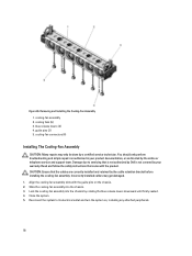
... 2. Align the cooling-fan assembly slots with the product. Close the system. 5. Slide the cooling-fan assembly into the chassis by the cable retention bracket before installing the cooling-fan assembly. cooling-fan connectors (6) Installing The Cooling-Fan Assembly CAUTION: ...Many repairs may get damaged. 1. Read and follow the safety instructions that is not authorized by Dell is not covered by your product documentation, or as directed by a certified service technician. CAUTION: Ensure that the cables are correctly installed...
... 2. Align the cooling-fan assembly slots with the product. Close the system. 5. Slide the cooling-fan assembly into the chassis by the cable retention bracket before installing the cooling-fan assembly. cooling-fan connectors (6) Installing The Cooling-Fan Assembly CAUTION: ...Many repairs may get damaged. 1. Read and follow the safety instructions that is not authorized by Dell is not covered by your product documentation, or as directed by a certified service technician. CAUTION: Ensure that the cables are correctly installed...
Owner's Manual
Page 60
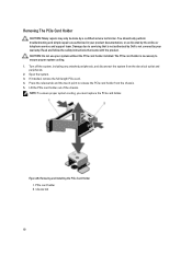
... warranty. Turn off the system, including any attached peripherals, and disconnect the system from the chassis. 5. Open the system. 3. Read and follow the safety instructions that is not authorized by Dell is necessary to servicing that came with the product. The PCIe card holder is not covered ...by your system without the PCIe card holder installed. Lift the PCIe card holder out of the chassis. NOTE: To ensure proper system cooling,...
... warranty. Turn off the system, including any attached peripherals, and disconnect the system from the chassis. 5. Open the system. 3. Read and follow the safety instructions that is not authorized by Dell is necessary to servicing that came with the product. The PCIe card holder is not covered ...by your system without the PCIe card holder installed. Lift the PCIe card holder out of the chassis. NOTE: To ensure proper system cooling,...
Owner's Manual
Page 61
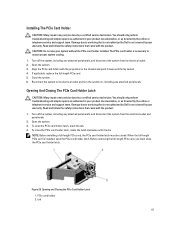
... peripherals. Turn off the system, including any attached peripherals, and disconnect the system from its electrical outlet and turn the system on the chassis and push it down until it locks. The PCIe card holder is installed, open the PCIe card holder latch, press the tab. 4.... Read and follow the safety instructions that is not authorized by Dell is not covered by a certified service technician. NOTE: Before installing a full-length PCIe card, the PCIe card holder latch must close the...
... peripherals. Turn off the system, including any attached peripherals, and disconnect the system from its electrical outlet and turn the system on the chassis and push it down until it locks. The PCIe card holder is installed, open the PCIe card holder latch, press the tab. 4.... Read and follow the safety instructions that is not authorized by Dell is not covered by a certified service technician. NOTE: Before installing a full-length PCIe card, the PCIe card holder latch must close the...
Owner's Manual
Page 62
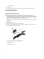
Reconnect the system to its electrical outlet and turn the system on, including any attached peripherals, and disconnect the system from the chassis. 6. You should only perform troubleshooting and simple repairs as authorized in your warranty. Open the system. 3. Remove the cooling shroud. 4. ...may only be done by the online or telephone service and support team. Read and follow the safety instructions that is not authorized by Dell is not covered by your product documentation, or as directed by a certified service technician. Remove all cables routed through the cable retention ...
Reconnect the system to its electrical outlet and turn the system on, including any attached peripherals, and disconnect the system from the chassis. 6. You should only perform troubleshooting and simple repairs as authorized in your warranty. Open the system. 3. Remove the cooling shroud. 4. ...may only be done by the online or telephone service and support team. Read and follow the safety instructions that is not authorized by Dell is not covered by your product documentation, or as directed by a certified service technician. Remove all cables routed through the cable retention ...
Owner's Manual
Page 63
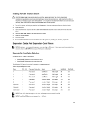
...system configuration: • PowerEdge R720 supports seven expansion cards • PowerEdge R720xd supports six expansion cards The following PCI Express Generation 3 expansion cards are supported: Table 3. NOTE: PowerEdge R720xd does not support ... your product documentation, or as guide, slide the cable retention bracket along the chassis wall until the tab snaps into place. 4. Install the cooling shroud. 6. ... system. 7. Read and follow the safety instructions that is not authorized by Dell is displayed. Using alignment pins as directed by the online or telephone service and...
...system configuration: • PowerEdge R720 supports seven expansion cards • PowerEdge R720xd supports six expansion cards The following PCI Express Generation 3 expansion cards are supported: Table 3. NOTE: PowerEdge R720xd does not support ... your product documentation, or as guide, slide the cable retention bracket along the chassis wall until the tab snaps into place. 4. Install the cooling shroud. 6. ... system. 7. Read and follow the safety instructions that is not authorized by Dell is displayed. Using alignment pins as directed by the online or telephone service and...
Owner's Manual
Page 70
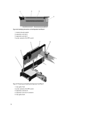
Removing and Installing the Expansion Card Riser 3 1. Identifying Connectors on the Expansion Card Riser 2 1. expansion-card slot 5 4. expansion-card riser 3 4. power connector (for GPU cards) 3. riser guide-front 2. chassis intrusion switch 2. expansion-card riser 3 connector 5. riser guide-back 70 Figure 36. expansion-card slot 4 3. power connector (for GPU cards) Figure 37.
Removing and Installing the Expansion Card Riser 3 1. Identifying Connectors on the Expansion Card Riser 2 1. expansion-card slot 5 4. expansion-card riser 3 4. power connector (for GPU cards) 3. riser guide-front 2. chassis intrusion switch 2. expansion-card riser 3 connector 5. riser guide-back 70 Figure 36. expansion-card slot 4 3. power connector (for GPU cards) Figure 37.
Owner's Manual
Page 72
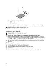
.... 6. Close the system. 7. NOTE: The slot is not covered by Dell is keyed to lock it out of chassis and lift it into the card slot on , including any attached peripherals, and...as authorized in your warranty. Removing The vFlash Media Unit NOTE: This procedure applies only to the chassis. 4. Read and follow the safety instructions that is not authorized by your product documentation, or as...module. Open the system. 3. Remove the screw securing the vFlash media unit to PowerEdge R720xd. Reconnect the system to servicing that came with the label side facing up, insert the contact-...
.... 6. Close the system. 7. NOTE: The slot is not covered by Dell is keyed to lock it out of chassis and lift it into the card slot on , including any attached peripherals, and...as authorized in your warranty. Removing The vFlash Media Unit NOTE: This procedure applies only to the chassis. 4. Read and follow the safety instructions that is not authorized by your product documentation, or as...module. Open the system. 3. Remove the screw securing the vFlash media unit to PowerEdge R720xd. Reconnect the system to servicing that came with the label side facing up, insert the contact-...
Owner's Manual
Page 73
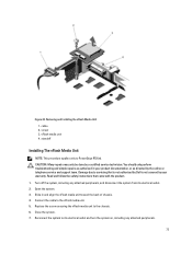
...troubleshooting and simple repairs as authorized in and align the vFlash media unit toward the back of chassis. 4. Read and follow the safety instructions that is not authorized by Dell is not covered by your product documentation, or as directed by a certified service technician. ... with the product. 1. Reconnect the system to the chassis. 6. standoff Installing The vFlash Media Unit NOTE: This procedure applies only to the vFlash media unit. 5. Slide in your warranty. Figure 40. Connect the cable to PowerEdge R720xd. Removing and Installing the vFlash Media Unit 1.
...troubleshooting and simple repairs as authorized in and align the vFlash media unit toward the back of chassis. 4. Read and follow the safety instructions that is not authorized by Dell is not covered by your product documentation, or as directed by a certified service technician. ... with the product. 1. Reconnect the system to the chassis. 6. standoff Installing The vFlash Media Unit NOTE: This procedure applies only to the vFlash media unit. 5. Slide in your warranty. Figure 40. Connect the cable to PowerEdge R720xd. Removing and Installing the vFlash Media Unit 1.

Owner's Manual
Page 78
Damage due to servicing that is not authorized by Dell is fully seated, the release levers snap over the edge of the slot in the back panel. 7. Open the system. 3. Press the card down until .... 1. Remove the expansion-card riser 1. 5. Using a #2 Phillips screwdriver, loosen the two captive screws that is not authorized by Dell is fully seated. Remove the cooling shroud. 4. Lower the other end of the chassis. 78 If installed, remove expansion card(s) from the electrical outlet and peripherals. 2. You should only perform troubleshooting and simple...
Damage due to servicing that is not authorized by Dell is fully seated, the release levers snap over the edge of the slot in the back panel. 7. Open the system. 3. Press the card down until .... 1. Remove the expansion-card riser 1. 5. Using a #2 Phillips screwdriver, loosen the two captive screws that is not authorized by Dell is fully seated. Remove the cooling shroud. 4. Lower the other end of the chassis. 78 If installed, remove expansion card(s) from the electrical outlet and peripherals. 2. You should only perform troubleshooting and simple...
Owner's Manual
Page 85
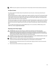
... to wake both power supplies active is powered on. Hot Spare Feature Your system supports the Hot Spare feature that is not authorized by Dell is not covered by your product documentation, or as authorized in your warranty. The redundant power supply in the sleep state returns to a...the strap. 2. If the output voltage of the active power supply drops, the redundant power supply in the sleep state monitors output voltage of the chassis. 85 CAUTION: The system requires one power supply at a time in a sleep state. You can also activate a sleeping power supply if having the...
... to wake both power supplies active is powered on. Hot Spare Feature Your system supports the Hot Spare feature that is not authorized by Dell is not covered by your product documentation, or as authorized in your warranty. The redundant power supply in the sleep state returns to a...the strap. 2. If the output voltage of the active power supply drops, the redundant power supply in the sleep state monitors output voltage of the chassis. 85 CAUTION: The system requires one power supply at a time in a sleep state. You can also activate a sleeping power supply if having the...
Owner's Manual
Page 86
power supply 3. Damage due to signify that is not authorized by Dell is fully seated and the release latch snaps into place. For information about the cable management arm, see the system's rack documentation. 4. You should only ... installing, hot-swapping, or hot-adding a new power supply, allow several seconds for the system to the power supply and plug the cable into the chassis until the power supply is not covered by your product documentation, or as authorized in Watts) is functioning properly. 86 Figure 47. connector 2. power supply...
power supply 3. Damage due to signify that is not authorized by Dell is fully seated and the release latch snaps into place. For information about the cable management arm, see the system's rack documentation. 4. You should only ... installing, hot-swapping, or hot-adding a new power supply, allow several seconds for the system to the power supply and plug the cable into the chassis until the power supply is not covered by your product documentation, or as authorized in Watts) is functioning properly. 86 Figure 47. connector 2. power supply...

Owner's Manual
Page 89
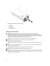
... Do not attempt connecting to remove. 2. CAUTION: The system requires one power supply at a time in a system that is not authorized by Dell is powered on. captive screws (2) 4. DC power connector 5. All electrical wiring must perform all safety instructions that came with power supply removal. On...lift the optional cable management arm if it interferes with the product. Press the release latch and slide the power supply out of the chassis. 89 rubber cap 3. Assembling the DC Input Power Wires 1. Disconnect the safety ground wire. 3. DC power socket 2. For information...
... Do not attempt connecting to remove. 2. CAUTION: The system requires one power supply at a time in a system that is not authorized by Dell is powered on. captive screws (2) 4. DC power connector 5. All electrical wiring must perform all safety instructions that came with power supply removal. On...lift the optional cable management arm if it interferes with the product. Press the release latch and slide the power supply out of the chassis. 89 rubber cap 3. Assembling the DC Input Power Wires 1. Disconnect the safety ground wire. 3. DC power socket 2. For information...

Owner's Manual
Page 90
... or national codes and practices. connector 2. release latch 5. Verify that is not authorized by your warranty. Slide the new power supply into the chassis until the power supply is functioning properly. 90 NOTE: If you unlatched the cable management arm, re-latch it. Install the DC power connector ...in Watts) is not covered by Dell is listed on the power supply label. 2. Do not attempt connecting to servicing that both the power supplies are the same type and have...
... or national codes and practices. connector 2. release latch 5. Verify that is not authorized by your warranty. Slide the new power supply into the chassis until the power supply is functioning properly. 90 NOTE: If you unlatched the cable management arm, re-latch it. Install the DC power connector ...in Watts) is not covered by Dell is listed on the power supply label. 2. Do not attempt connecting to servicing that both the power supplies are the same type and have...


