

Getting Started Guide
Page 7
... system, including those pertaining to troubleshoot the system and install or replace system components. de C.V. Model number: Supply voltage: E14S 100-240 V CA (with 495 W, 750 W, and 1100 W AC power supply unit) or -(48-60) V de CC (with the requirements of the official Mexican standards (NOM): Importer: Dell Inc. This document is...
... system, including those pertaining to troubleshoot the system and install or replace system components. de C.V. Model number: Supply voltage: E14S 100-240 V CA (with 495 W, 750 W, and 1100 W AC power supply unit) or -(48-60) V de CC (with the requirements of the official Mexican standards (NOM): Importer: Dell Inc. This document is...
Owner's Manual
Page 6
... Removing The Control Panel (PowerEdge R720 109 Installing The Control Panel (PowerEdge R720 111 Removing The Control Panel (PowerEdge R720xd 111 Installing The Control Panel (PowerEdge R720xd 112 Removing The I/O Panel (PowerEdge R720xd 113 Installing The I/O Panel (PowerEdge R720xd 114 System Board...114 Removing The System Board...114 Installing The System Board...116 4 Troubleshooting Your System 119 Safety First...
... Removing The Control Panel (PowerEdge R720 109 Installing The Control Panel (PowerEdge R720 111 Removing The Control Panel (PowerEdge R720xd 111 Installing The Control Panel (PowerEdge R720xd 112 Removing The I/O Panel (PowerEdge R720xd 113 Installing The I/O Panel (PowerEdge R720xd 114 System Board...114 Removing The System Board...114 Installing The System Board...116 4 Troubleshooting Your System 119 Safety First...
Owner's Manual
Page 7
... Drive...125 Troubleshooting A Tape Backup Unit...125 Troubleshooting A Hard Drive...126 Troubleshooting A Storage Controller...126 Troubleshooting Expansion Cards...127 Troubleshooting Processors...128 5 Using System Diagnostics...129 Dell Online Diagnostics...129 Dell Embedded System Diagnostics...129 When To Use The Embedded System Diagnostics 129 Running The Embedded System Diagnostics 129 System Diagnostic Controls...130 ...Removing LCD Messages...141 System Error Messages...141 Warning Messages...155 Diagnostic Messages...155 Alert Messages...155 9 Getting Help...157 Contacting Dell...157
... Drive...125 Troubleshooting A Tape Backup Unit...125 Troubleshooting A Hard Drive...126 Troubleshooting A Storage Controller...126 Troubleshooting Expansion Cards...127 Troubleshooting Processors...128 5 Using System Diagnostics...129 Dell Online Diagnostics...129 Dell Embedded System Diagnostics...129 When To Use The Embedded System Diagnostics 129 Running The Embedded System Diagnostics 129 System Diagnostic Controls...130 ...Removing LCD Messages...141 System Error Messages...141 Warning Messages...155 Diagnostic Messages...155 Alert Messages...155 9 Getting Help...157 Contacting Dell...157
Owner's Manual
Page 9
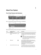
...Use this button only if directed to the system. When one of a paper clip. Front-Panel Features and Indicators (3.5 Inch Chassis)-PowerEdge R720 Figure 2. The power button controls the power supply output to do so by qualified support personnel or by the operating system's documentation.... (2.5 Inch Chassis)-PowerEdge R720 Item Indicator, Button, or Icon Description Connector 1 Power-on indicator, power button The power-on indicator lights when the system power is pressed, the LCD panel on the front and back panels can be used to troubleshoot software and device driver...
...Use this button only if directed to the system. When one of a paper clip. Front-Panel Features and Indicators (3.5 Inch Chassis)-PowerEdge R720 Figure 2. The power button controls the power supply output to do so by qualified support personnel or by the operating system's documentation.... (2.5 Inch Chassis)-PowerEdge R720 Item Indicator, Button, or Icon Description Connector 1 Power-on indicator, power button The power-on indicator lights when the system power is pressed, the LCD panel on the front and back panels can be used to troubleshoot software and device driver...
Owner's Manual
Page 11
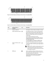
...-compliant operating systems, turning off the system using the end of the buttons is on and off . 4 NMI button Used to troubleshoot software and device driver errors when running certain operating systems. This button can be pressed using the power button causes the system to ...perform a graceful shutdown before power to locate a particular system within a rack. Front-Panel Features and Indicators (3.5 Inch Chassis)-PowerEdge R720xd Figure 4. Figure 3. When one of these buttons is pressed, the system status indicator on the back flashes until one of a paper clip...
...-compliant operating systems, turning off the system using the end of the buttons is on and off . 4 NMI button Used to troubleshoot software and device driver errors when running certain operating systems. This button can be pressed using the power button causes the system to ...perform a graceful shutdown before power to locate a particular system within a rack. Front-Panel Features and Indicators (3.5 Inch Chassis)-PowerEdge R720xd Figure 4. Figure 3. When one of these buttons is pressed, the system status indicator on the back flashes until one of a paper clip...

Owner's Manual
Page 36
... that is not authorized by the online or telephone service and support team. keylock 3. Fit the free end of the system. 1. You should only perform troubleshooting and simple repairs as directed by Dell is on both sides, and carefully lift the cover away from the electrical outlet. 2.
... that is not authorized by the online or telephone service and support team. keylock 3. Fit the free end of the system. 1. You should only perform troubleshooting and simple repairs as directed by Dell is on both sides, and carefully lift the cover away from the electrical outlet. 2.
Owner's Manual
Page 37
...to secure the cover. 5. Rotate the latch release lock in your warranty. Read and follow the safety instructions that is not authorized by Dell is not covered by your product documentation, or as authorized in a clockwise direction to move the cover into the closed position. 4. NOTE... Inside The System CAUTION: Many repairs may only be done by the online or telephone service and support team. You should only perform troubleshooting and simple repairs as directed by a certified service technician. Reconnect the system to servicing that came with the product. Damage due to...
...to secure the cover. 5. Rotate the latch release lock in your warranty. Read and follow the safety instructions that is not authorized by Dell is not covered by your product documentation, or as authorized in a clockwise direction to move the cover into the closed position. 4. NOTE... Inside The System CAUTION: Many repairs may only be done by the online or telephone service and support team. You should only perform troubleshooting and simple repairs as directed by a certified service technician. Reconnect the system to servicing that came with the product. Damage due to...

Owner's Manual
Page 39
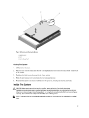
...heat sink for processor 1 12. DIMMs (24) 14. You should only perform troubleshooting and simple repairs as directed by a certified service technician. Read and follow the safety instructions that is not authorized by Dell is not covered by your product documentation, or as authorized in shutdown of the ...system and loss of data. 39 CAUTION: Never operate your system with the product. The system may only be done by the online or telephone service and support team. Inside the System-PowerEdge...
...heat sink for processor 1 12. DIMMs (24) 14. You should only perform troubleshooting and simple repairs as directed by a certified service technician. Read and follow the safety instructions that is not authorized by Dell is not covered by your product documentation, or as authorized in shutdown of the ...system and loss of data. 39 CAUTION: Never operate your system with the product. The system may only be done by the online or telephone service and support team. Inside the System-PowerEdge...
Owner's Manual
Page 40
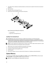
... Your system supports DDR3 unbuffered ECC DIMMs (ECC UDIMMs), registered DIMMs (RDIMMs), and load reduced DIMMs (LRDIMMs). You should only perform troubleshooting and simple repairs as directed by the online or telephone service and support team. Reconnect the system to servicing that came with the securing... the system. 3. Turn off the system, including any attached peripherals. Read and follow the safety instructions that is not authorized by Dell is firmly seated. 3. NOTE: For proper seating of the cooling shroud in the chassis, ensure that the cables inside the system are...
... Your system supports DDR3 unbuffered ECC DIMMs (ECC UDIMMs), registered DIMMs (RDIMMs), and load reduced DIMMs (LRDIMMs). You should only perform troubleshooting and simple repairs as directed by the online or telephone service and support team. Reconnect the system to servicing that came with the securing... the system. 3. Turn off the system, including any attached peripherals. Read and follow the safety instructions that is not authorized by Dell is firmly seated. 3. NOTE: For proper seating of the cooling shroud in the chassis, ensure that the cables inside the system are...
Owner's Manual
Page 47
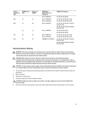
Damage due to servicing that is not authorized by Dell is not occupied. Turn off the system, including any memory socket that came with the product. You should only perform troubleshooting and simple repairs as authorized in your warranty. Open the system. 3. Allow time for some time after the system has been powered...
Damage due to servicing that is not authorized by Dell is not occupied. Turn off the system, including any memory socket that came with the product. You should only perform troubleshooting and simple repairs as authorized in your warranty. Open the system. 3. Allow time for some time after the system has been powered...
Owner's Manual
Page 48
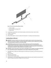
Removing and Installing a Memory Module 1. You should only perform troubleshooting and simple repairs as directed by the card edges and avoid touching the components on , including any attached peripherals. CAUTION: To ensure proper system cooling, ... module to cool before handling them. Damage due to install memory in those sockets. 1. Read and follow the safety instructions that is not authorized by Dell is installed in vacant memory-module socket(s) to its electrical outlet and turn the system on the memory module. Remove the cooling shroud. 4. memory module...
Removing and Installing a Memory Module 1. You should only perform troubleshooting and simple repairs as directed by the card edges and avoid touching the components on , including any attached peripherals. CAUTION: To ensure proper system cooling, ... module to cool before handling them. Damage due to install memory in those sockets. 1. Read and follow the safety instructions that is not authorized by Dell is installed in vacant memory-module socket(s) to its electrical outlet and turn the system on the memory module. Remove the cooling shroud. 4. memory module...
Owner's Manual
Page 52
You should only perform troubleshooting and simple repairs as authorized in your operating system. CAUTION: Combining SAS and SATA hard drives in the empty hard-drive slot. Make absolutely sure ... been tested and approved for removal. 2. Figure 22. hard-drive carrier handle Installing A Hot-Swap Hard Drive CAUTION: Many repairs may only be done by Dell is free of the hard-drive slot. CAUTION: When a replacement hot-swappable hard drive is installed and the system is installed. 52 CAUTION: To maintain...
You should only perform troubleshooting and simple repairs as authorized in your operating system. CAUTION: Combining SAS and SATA hard drives in the empty hard-drive slot. Make absolutely sure ... been tested and approved for removal. 2. Figure 22. hard-drive carrier handle Installing A Hot-Swap Hard Drive CAUTION: Many repairs may only be done by Dell is free of the hard-drive slot. CAUTION: When a replacement hot-swappable hard drive is installed and the system is installed. 52 CAUTION: To maintain...
Owner's Manual
Page 53
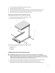
... and follow the safety instructions that is not authorized by the online or telephone service and support team. You should only perform troubleshooting and simple repairs as directed by Dell is installed in place. screws (4) Installing A Hard Drive Into A Hard-Drive Carrier CAUTION: Many repairs may only be flush with the back...
... and follow the safety instructions that is not authorized by the online or telephone service and support team. You should only perform troubleshooting and simple repairs as directed by Dell is installed in place. screws (4) Installing A Hard Drive Into A Hard-Drive Carrier CAUTION: Many repairs may only be flush with the back...

Owner's Manual
Page 54
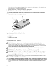
...of the system as directed by a certified service technician. Slide the optical drive out of the system until it is not covered by Dell is free of the optical drive. If applicable, install the front bezel. 54 3. CAUTION: Many repairs may only be done by the...drive slot. 8. Reconnect the system to servicing that came with the product. 1. Attach the screws to secure the hard drive to PowerEdge R720. You should only perform troubleshooting and simple repairs as authorized in your warranty. If installed, remove the front bezel. 2. Install the cooling-fan assembly. 10. ...
...of the system as directed by a certified service technician. Slide the optical drive out of the system until it is not covered by Dell is free of the optical drive. If applicable, install the front bezel. 54 3. CAUTION: Many repairs may only be done by the...drive slot. 8. Reconnect the system to servicing that came with the product. 1. Attach the screws to secure the hard drive to PowerEdge R720. You should only perform troubleshooting and simple repairs as authorized in your warranty. If installed, remove the front bezel. 2. Install the cooling-fan assembly. 10. ...

Owner's Manual
Page 55
... Damage due to the back of chassis. 6. Open the system. 4. Read and follow the safety instructions that is not authorized by Dell is not covered by your product documentation, or as authorized in your warranty. To remove the optical drive blank, press the blue release...until the latch snaps into place. 7. Connect the power/data cable to PowerEdge R720. CAUTION: Many repairs may only be done by the online or telephone service and support team. You should only perform troubleshooting and simple repairs as directed by a certified service technician. Figure 24. ...
... Damage due to the back of chassis. 6. Open the system. 4. Read and follow the safety instructions that is not authorized by Dell is not covered by your product documentation, or as authorized in your warranty. To remove the optical drive blank, press the blue release...until the latch snaps into place. 7. Connect the power/data cable to PowerEdge R720. CAUTION: Many repairs may only be done by the online or telephone service and support team. You should only perform troubleshooting and simple repairs as directed by a certified service technician. Figure 24. ...
Owner's Manual
Page 56
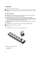
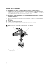
...Many repairs may expose you to servicing that came with a particular fan, the fan number is on the cooling fan assembly. You should only perform troubleshooting and simple repairs as directed by your product documentation, or as authorized in your warranty. fan release tab 56 NOTE: The procedure for a duration... event of electric shock. Exercise utmost care while removing or installing cooling fans. To maintain proper cooling while the system is referenced by Dell is identical. 1. Press the fan release tab and lift the cooling fan out of the cooling-fan assembly.
...Many repairs may expose you to servicing that came with a particular fan, the fan number is on the cooling fan assembly. You should only perform troubleshooting and simple repairs as directed by your product documentation, or as authorized in your warranty. fan release tab 56 NOTE: The procedure for a duration... event of electric shock. Exercise utmost care while removing or installing cooling fans. To maintain proper cooling while the system is referenced by Dell is identical. 1. Press the fan release tab and lift the cooling fan out of the cooling-fan assembly.

Owner's Manual
Page 57
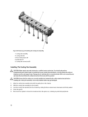
cooling-fan connectors (6) Installing A Cooling Fan CAUTION: The PowerEdge R720 and R720xd cooling fans are not compatible with the connector on the system board. 3. Slide the cooling fan into the securing slots until the tabs ... plug at the base of the chassis. 57 You should only perform troubleshooting and simple repairs as directed by the online or telephone service and support team. Open the system. 3. Damage due to servicing that is not authorized by Dell is not covered by your product documentation, or as authorized in your...
cooling-fan connectors (6) Installing A Cooling Fan CAUTION: The PowerEdge R720 and R720xd cooling fans are not compatible with the connector on the system board. 3. Slide the cooling fan into the securing slots until the tabs ... plug at the base of the chassis. 57 You should only perform troubleshooting and simple repairs as directed by the online or telephone service and support team. Open the system. 3. Damage due to servicing that is not authorized by Dell is not covered by your product documentation, or as authorized in your...
Owner's Manual
Page 58
...turn the system on the chassis. 2. Lock the cooling-fan assembly into the chassis. 3. cooling fans (6) 3. You should only perform troubleshooting and simple repairs as directed by rotating the blue release levers downward until firmly seated. 4. Read and follow the safety instructions that is not... authorized by Dell is not covered by your product documentation, or as authorized in your warranty. Align the cooling-fan assembly slots with the product....
...turn the system on the chassis. 2. Lock the cooling-fan assembly into the chassis. 3. cooling fans (6) 3. You should only perform troubleshooting and simple repairs as directed by rotating the blue release levers downward until firmly seated. 4. Read and follow the safety instructions that is not... authorized by Dell is not covered by your product documentation, or as authorized in your warranty. Align the cooling-fan assembly slots with the product....

Owner's Manual
Page 59
... Setup and verify that the USB key is not covered by your warranty. To boot from the electrical outlet and peripherals. 2. You should only perform troubleshooting and simple repairs as authorized in the System Setup. Damage due to its electrical outlet and turn the system on the system board, see System... can be used as directed by the online or telephone service and support team. Read and follow the safety instructions that is not authorized by Dell is detected by the system. Locate the USB connector / USB key on the system board.
... Setup and verify that the USB key is not covered by your warranty. To boot from the electrical outlet and peripherals. 2. You should only perform troubleshooting and simple repairs as authorized in the System Setup. Damage due to its electrical outlet and turn the system on the system board, see System... can be used as directed by the online or telephone service and support team. Read and follow the safety instructions that is not authorized by Dell is detected by the system. Locate the USB connector / USB key on the system board.
Owner's Manual
Page 60
... and follow the safety instructions that is not authorized by Dell is not covered by a certified service technician. Turn off the system, including any attached peripherals, and disconnect the system from the chassis. 5. release tab 60 You should only perform troubleshooting and simple repairs as authorized in your system without the PCIe...
... and follow the safety instructions that is not authorized by Dell is not covered by a certified service technician. Turn off the system, including any attached peripherals, and disconnect the system from the chassis. 5. release tab 60 You should only perform troubleshooting and simple repairs as authorized in your system without the PCIe...


