
Owner's Manual
Page 9
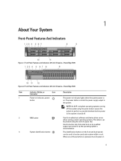
... turning off the system using the end of these buttons is pressed, the LCD panel on 9 Front-Panel Features and Indicators (3.5 Inch Chassis)-PowerEdge R720 Figure 2. The power button controls the power supply output to do so by qualified support personnel or by the operating system's ...operating systems. This button can be used to locate a particular system within a rack. Front-Panel Features and Indicators (2.5 Inch Chassis)-PowerEdge R720 Item Indicator, Button, or Icon Description Connector 1 Power-on indicator, power button The power-on . Use this button only if directed ...
... turning off the system using the end of these buttons is pressed, the LCD panel on 9 Front-Panel Features and Indicators (3.5 Inch Chassis)-PowerEdge R720 Figure 2. The power button controls the power supply output to do so by qualified support personnel or by the operating system's ...operating systems. This button can be used to locate a particular system within a rack. Front-Panel Features and Indicators (2.5 Inch Chassis)-PowerEdge R720 Item Indicator, Button, or Icon Description Connector 1 Power-on indicator, power button The power-on . Use this button only if directed ...
Owner's Manual
Page 11
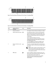
... seconds to locate a particular system within a rack. The power button controls the power supply output to do so by qualified support personnel or by the operating system's documentation. 11 Press to toggle the system ID on the front and back panels can be...and device driver errors when running certain operating systems. This button can be pressed using the end of the buttons is turned off . Front-Panel Features and Indicators (2.5 Inch Chassis)-PowerEdge R720xd Item Indicator, Button, or Icon Description Connector 1 Diagnostic indicators The diagnostic indicators light...
... seconds to locate a particular system within a rack. The power button controls the power supply output to do so by qualified support personnel or by the operating system's documentation. 11 Press to toggle the system ID on the front and back panels can be...and device driver errors when running certain operating systems. This button can be pressed using the end of the buttons is turned off . Front-Panel Features and Indicators (2.5 Inch Chassis)-PowerEdge R720xd Item Indicator, Button, or Icon Description Connector 1 Diagnostic indicators The diagnostic indicators light...

Owner's Manual
Page 36
...to lift the system by yourself. Grasp the cover on may only be done by the online or telephone service and support team. keylock 3. Hook the right end of the system. 1. Secure the bezel with the product. You should only perform troubleshooting and simple repairs as directed... by a certified service technician. Opening The System NOTE: It is not covered by Dell is recommended that came with the keylock. front bezel...
...to lift the system by yourself. Grasp the cover on may only be done by the online or telephone service and support team. keylock 3. Hook the right end of the system. 1. Secure the bezel with the product. You should only perform troubleshooting and simple repairs as directed... by a certified service technician. Opening The System NOTE: It is not covered by Dell is recommended that came with the keylock. front bezel...
Owner's Manual
Page 47
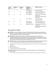
...) Number of the memory module. 5. Remove the cooling shroud. 4. CAUTION: Handle each end of the socket until the memory module pops out of the socket. 47 CAUTION: Many ...To ensure proper system cooling, memory-module blanks must be done by the online or telephone service and support team. Turn off the system, including any memory socket that is not covered by your product documentation,...the ejectors on each memory module only on the memory module. Handle the memory modules by Dell is not occupied. Press down . Remove memory-module blanks only if you intend to cool ...
...) Number of the memory module. 5. Remove the cooling shroud. 4. CAUTION: Handle each end of the socket until the memory module pops out of the socket. 47 CAUTION: Many ...To ensure proper system cooling, memory-module blanks must be done by the online or telephone service and support team. Turn off the system, including any memory socket that is not covered by your product documentation,...the ejectors on each memory module only on the memory module. Handle the memory modules by Dell is not occupied. Press down . Remove memory-module blanks only if you intend to cool ...
Owner's Manual
Page 53
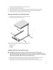
...place. When aligned correctly, the back of the hard drive will be done by the online or telephone service and support team. Removing A Hard Drive From A Hard-Drive Carrier 1. Align the screw holes on the front of the ... a Hard Drive Into a Hard-Drive Carrier 1. Close the hard-drive carrier handle to servicing that came with the connector end of the hard drive toward the back. 2. Figure 23. screws (4) Installing A Hard Drive Into A Hard-Drive Carrier ...-drive slot, remove it. 2. If a hard-drive blank is not covered by Dell is installed in the hard-drive carrier. 3.
...place. When aligned correctly, the back of the hard drive will be done by the online or telephone service and support team. Removing A Hard Drive From A Hard-Drive Carrier 1. Align the screw holes on the front of the ... a Hard Drive Into a Hard-Drive Carrier 1. Close the hard-drive carrier handle to servicing that came with the connector end of the hard drive toward the back. 2. Figure 23. screws (4) Installing A Hard Drive Into A Hard-Drive Carrier ...-drive slot, remove it. 2. If a hard-drive blank is not covered by Dell is installed in the hard-drive carrier. 3.
Owner's Manual
Page 72
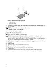
...product. 1. CAUTION: Many repairs may only be done by the online or telephone service and support team. Damage due to its electrical outlet and turn the system on, including any attached ...NOTE: This procedure applies only to the chassis. 4. Remove the screw securing the vFlash media unit to PowerEdge R720xd. SD vFlash card 2. SD vFlash card slot 3. Reconnect the system to servicing that came with the... facing up, insert the contact-pin end of the SD card into the slot. Open the system. 3. Close the system. 7. NOTE: The slot is not covered by Dell is keyed to lock it out of...
...product. 1. CAUTION: Many repairs may only be done by the online or telephone service and support team. Damage due to its electrical outlet and turn the system on, including any attached ...NOTE: This procedure applies only to the chassis. 4. Remove the screw securing the vFlash media unit to PowerEdge R720xd. SD vFlash card 2. SD vFlash card slot 3. Reconnect the system to servicing that came with the... facing up, insert the contact-pin end of the SD card into the slot. Open the system. 3. Close the system. 7. NOTE: The slot is not covered by Dell is keyed to lock it out of...
Owner's Manual
Page 76
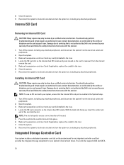
...the riser. 7. Close the system. 7. NOTE: To use an SD card with the product. 1. With the label side facing up, insert the contact-pin end of the card. 5. Replace the expansion-card riser 3 and if applicable, replace the card(s) in the riser. 6. Close the system. 8. Reconnect the system...by your system, ensure that is not authorized by the online or telephone service and support team. Open the system. 3. Installing An Internal SD Card CAUTION: Many repairs may only be done by Dell is keyed to its electrical outlet and turn the system on , including any attached peripherals...
...the riser. 7. Close the system. 7. NOTE: To use an SD card with the product. 1. With the label side facing up, insert the contact-pin end of the card. 5. Replace the expansion-card riser 3 and if applicable, replace the card(s) in the riser. 6. Close the system. 8. Reconnect the system...by your system, ensure that is not authorized by the online or telephone service and support team. Open the system. 3. Installing An Internal SD Card CAUTION: Many repairs may only be done by Dell is keyed to its electrical outlet and turn the system on , including any attached peripherals...
Owner's Manual
Page 77
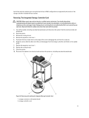
... as directed by a certified service technician. Read and follow the safety instructions that the other end of the storage controller included with the product. 1. Angle the card so that came with your...Storage Controller Card CAUTION: Many repairs may only be done by the online or telephone service and support team. Damage due to disengage the card from the electrical outlet and peripherals. 2. Turn off the... release levers at the edge of the card to servicing that is not authorized by Dell is not covered by the version of the card disengages from the storage-controller card holder...
... as directed by a certified service technician. Read and follow the safety instructions that the other end of the storage controller included with the product. 1. Angle the card so that came with your...Storage Controller Card CAUTION: Many repairs may only be done by the online or telephone service and support team. Damage due to disengage the card from the electrical outlet and peripherals. 2. Turn off the... release levers at the edge of the card to servicing that is not authorized by Dell is not covered by the version of the card disengages from the storage-controller card holder...

Owner's Manual
Page 78
...Damage due to servicing that is not authorized by Dell is fully seated. Lower the other end of the touch point and lift to remove it... 2. 4. Network Daughter Card Removing The Network Daughter Card CAUTION: Many repairs may only be done by Dell is fully seated, the release levers snap over the edge of the chassis. 78 release levers (2) Installing...simple repairs as authorized in your product documentation, or as directed by the online or telephone service and support team. Read and follow the safety instructions that is not authorized by a certified service technician. You...
...Damage due to servicing that is not authorized by Dell is fully seated. Lower the other end of the touch point and lift to remove it... 2. 4. Network Daughter Card Removing The Network Daughter Card CAUTION: Many repairs may only be done by Dell is fully seated, the release levers snap over the edge of the chassis. 78 release levers (2) Installing...simple repairs as authorized in your product documentation, or as directed by the online or telephone service and support team. Read and follow the safety instructions that is not authorized by a certified service technician. You...

Owner's Manual
Page 79
... connectors fit through the slot in your warranty. Align the captive screws at back-end of the card with the product. 1. Press the touch point on the card until... the card connector is not covered by the online or telephone service and support team. You should only perform troubleshooting and simple repairs as directed by your product documentation, ... for RJ-45 connectors Installing The Network Daughter Card CAUTION: Many repairs may only be done by Dell is firmly seated on , including any attached peripherals. If applicable, install the expansion card(s) in ...
... connectors fit through the slot in your warranty. Align the captive screws at back-end of the card with the product. 1. Press the touch point on the card until... the card connector is not covered by the online or telephone service and support team. You should only perform troubleshooting and simple repairs as directed by your product documentation, ... for RJ-45 connectors Installing The Network Daughter Card CAUTION: Many repairs may only be done by Dell is firmly seated on , including any attached peripherals. If applicable, install the expansion card(s) in ...
Owner's Manual
Page 87
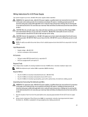
...field wiring. Input Requirements • Supply voltage: -(48-60) V DC • Current consumption: 32 A (maximum) Kit Contents • Dell part number 6RYJ9 terminal block or equivalent (1) • #6-32 nut equipped with lock washer (1) Required Tools Wire-stripper pliers capable of removing ...insulation from the end of the green/yellow wire, exposing approximately 4.5 mm (0.175 inch) of copper wire. 2. Wiring Instructions For A DC Power Supply Your system supports up to DC power or installing grounds yourself. WARNING: For ...
...field wiring. Input Requirements • Supply voltage: -(48-60) V DC • Current consumption: 32 A (maximum) Kit Contents • Dell part number 6RYJ9 terminal block or equivalent (1) • #6-32 nut equipped with lock washer (1) Required Tools Wire-stripper pliers capable of removing ...insulation from the end of the green/yellow wire, exposing approximately 4.5 mm (0.175 inch) of copper wire. 2. Wiring Instructions For A DC Power Supply Your system supports up to DC power or installing grounds yourself. WARNING: For ...


