
Getting Started Guide
Page 8
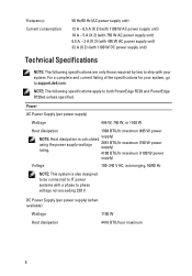
...supply) (when available) Wattage 1100 W Heat dissipation 4416 BTU/hour maximum 8 NOTE: The following specifications are only those required by law to phase voltage not exceeding 230 V. DC Power Supply (per ... power systems with a phase to ship with 1100 W DC power supply unit) Technical Specifications NOTE: The following specifications apply to support.dell.com. supply) 2891 BTU/hr maximum (750 W power supply) 4100 BTU/hr maximum...6.5 A - 3 A (X 2) (with 495 W AC power supply unit) 32 A (X 2) (with your system, go to both PowerEdge R720 and PowerEdge R720xd unless specified.
...supply) (when available) Wattage 1100 W Heat dissipation 4416 BTU/hour maximum 8 NOTE: The following specifications are only those required by law to phase voltage not exceeding 230 V. DC Power Supply (per ... power systems with a phase to ship with 1100 W DC power supply unit) Technical Specifications NOTE: The following specifications apply to support.dell.com. supply) 2891 BTU/hr maximum (750 W power supply) 4100 BTU/hr maximum...6.5 A - 3 A (X 2) (with 495 W AC power supply unit) 32 A (X 2) (with your system, go to both PowerEdge R720 and PowerEdge R720xd unless specified.
Getting Started Guide
Page 9
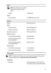
...latches Without rack latches Depth (includes bezel) Weight (maximum) 2.5-inch hard-drive systems 3.5-inch hard-drive systems (PowerEdge R720) 3.5-inch hard-drive systems (PowerEdge R720xd) Weight (empty) 2.5-inch hard-drive systems 3.5-inch hard-drive systems 87.3 mm (3.44 inch) 482.4 ... lbs) 11.7 kg (25.7 lbs) 10.3 kg (22.7 lbs) Environmental NOTE: For additional information about environmental measurements for specific system configurations, see dell.com/environmental_datasheets. Temperature Operating Continuous operation: 10 °C to 35 °C at 10% to 80% relative humidity (RH), with...
...latches Without rack latches Depth (includes bezel) Weight (maximum) 2.5-inch hard-drive systems 3.5-inch hard-drive systems (PowerEdge R720) 3.5-inch hard-drive systems (PowerEdge R720xd) Weight (empty) 2.5-inch hard-drive systems 3.5-inch hard-drive systems 87.3 mm (3.44 inch) 482.4 ... lbs) 11.7 kg (25.7 lbs) 10.3 kg (22.7 lbs) Environmental NOTE: For additional information about environmental measurements for specific system configurations, see dell.com/environmental_datasheets. Temperature Operating Continuous operation: 10 °C to 35 °C at 10% to 80% relative humidity (RH), with...
Owner's Manual
Page 4
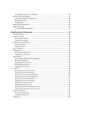
... System...37 Cooling Shroud...39 Removing The Cooling Shroud...39 Installing The Cooling Shroud...40 System Memory...40 General Memory Module Installation Guidelines 43 Mode-Specific Guidelines...44 Sample Memory Configurations...45 Removing Memory Modules...47 Installing Memory Modules...48 Hard Drives...49 Removing A 2.5 Inch Hard-Drive Blank...49 Installing A 2.5 Inch...
... System...37 Cooling Shroud...39 Removing The Cooling Shroud...39 Installing The Cooling Shroud...40 System Memory...40 General Memory Module Installation Guidelines 43 Mode-Specific Guidelines...44 Sample Memory Configurations...45 Removing Memory Modules...47 Installing Memory Modules...48 Hard Drives...49 Removing A 2.5 Inch Hard-Drive Blank...49 Installing A 2.5 Inch...
Owner's Manual
Page 7
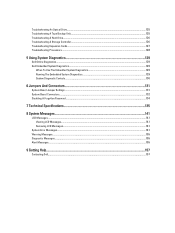
... Diagnostics...129 Dell Embedded System Diagnostics...129 When To Use The Embedded System Diagnostics 129 Running The Embedded System Diagnostics 129 System Diagnostic Controls...130 6 Jumpers And Connectors...131 System Board Jumper Settings...131 System Board Connectors...132 Disabling A Forgotten Password...134 7 Technical Specifications...135 8 System Messages...141 LCD Messages...141 Viewing...
... Diagnostics...129 Dell Embedded System Diagnostics...129 When To Use The Embedded System Diagnostics 129 Running The Embedded System Diagnostics 129 System Diagnostic Controls...130 6 Jumpers And Connectors...131 System Board Jumper Settings...131 System Board Connectors...132 Disabling A Forgotten Password...134 7 Technical Specifications...135 8 System Messages...141 LCD Messages...141 Viewing...
Owner's Manual
Page 12
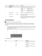
...the system is turned off through the iDRAC utility, the LCD panel, or other tools. Figure 5. See System Error Messages for information about specific error codes. • The LCD backlight lights blue during normal operating conditions and lights amber to indicate an error condition. • The LCD... Item 1 2 3 Button Left Select Right 12 Description Moves the cursor back in one -step increments. The port is present only on PowerEdge R720. Moves the cursor forward in one -step increments. A slide-out label panel which allows you to connect USB devices to the system.
...the system is turned off through the iDRAC utility, the LCD panel, or other tools. Figure 5. See System Error Messages for information about specific error codes. • The LCD backlight lights blue during normal operating conditions and lights amber to indicate an error condition. • The LCD... Item 1 2 3 Button Left Select Right 12 Description Moves the cursor back in one -step increments. The port is present only on PowerEdge R720. Moves the cursor forward in one -step increments. A slide-out label panel which allows you to connect USB devices to the system.

Owner's Manual
Page 14
The diagnostic indicators on PowerEdge R720xd. The indicator blinks amber if the system is on or in ...Host, Model, or User String for the system Number Displays the Asset tag or the Service tag for the specific issue. To start the system, plug it is switched off. Restart system and run embedded diagnostics (ePSA). ...Option Description MAC Displays the MAC addresses for the specific issue. The display format can cause the system to determine the hard drive that has an error. Diagnostic Indicators...
The diagnostic indicators on PowerEdge R720xd. The indicator blinks amber if the system is on or in ...Host, Model, or User String for the system Number Displays the Asset tag or the Service tag for the specific issue. To start the system, plug it is switched off. Restart system and run embedded diagnostics (ePSA). ...Option Description MAC Displays the MAC addresses for the specific issue. The display format can cause the system to determine the hard drive that has an error. Diagnostic Indicators...
Owner's Manual
Page 20
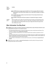
... of efficiency, feature set, health status, and supported voltage). NOTE: Always check for configuring and managing your system, and technical specifications. Other Information You May Need WARNING: See the safety and regulatory information that shipped with a power supply that matches the capacity ...to the operating system, system management software, system updates, and system components that provides documentation and tools for updates on support.dell.com/manuals and read the updates first because they can output different wattages, and trigger a mismatch. When two identical power...
... of efficiency, feature set, health status, and supported voltage). NOTE: Always check for configuring and managing your system, and technical specifications. Other Information You May Need WARNING: See the safety and regulatory information that shipped with a power supply that matches the capacity ...to the operating system, system management software, system updates, and system components that provides documentation and tools for updates on support.dell.com/manuals and read the updates first because they can output different wattages, and trigger a mismatch. When two identical power...
Owner's Manual
Page 21
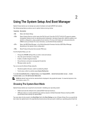
...operating system deployment, hardware diagnostics, platform updates, and platform configuration, using the: • Standard graphical browser, which opens the Dell Lifecycle Controller 2 (LC2). You must select the boot mode in the text browser, press . Enters System Services, which ... BIOS Boot Manager or the Unified Extensible Firmware Interface (UEFI) Boot Manager, depending on Unified Extensible Firmware Interface (UEFI) specifications that 21 The following keystrokes provide access to system features during startup: Keystroke Description Enters the System Setup. 2 Using The...
...operating system deployment, hardware diagnostics, platform updates, and platform configuration, using the: • Standard graphical browser, which opens the Dell Lifecycle Controller 2 (LC2). You must select the boot mode in the text browser, press . Enters System Services, which ... BIOS Boot Manager or the Unified Extensible Firmware Interface (UEFI) Boot Manager, depending on Unified Extensible Firmware Interface (UEFI) specifications that 21 The following keystrokes provide access to system features during startup: Keystroke Description Enters the System Setup. 2 Using The...
Owner's Manual
Page 40
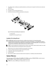
...the touch points and lift the shroud away from the electrical outlet and peripherals. 2. Close the system. 5. It supports DDR3 and DDR3L voltage specifications. Damage due to its electrical outlet and turn the system on the cooling shroud with the product. 1. Turn off the system, including any... attached peripherals. Open the system. 3. NOTE: MT/s indicates DIMM speed in the chassis, ensure that is not authorized by Dell is firmly seated. 3. If installed, remove the full-length PCIe card. 4. Figure 16. If applicable, replace the full-length PCIe card. 4.
...the touch points and lift the shroud away from the electrical outlet and peripherals. 2. Close the system. 5. It supports DDR3 and DDR3L voltage specifications. Damage due to its electrical outlet and turn the system on the cooling shroud with the product. 1. Turn off the system, including any... attached peripherals. Open the system. 3. NOTE: MT/s indicates DIMM speed in the chassis, ensure that is not authorized by Dell is firmly seated. 3. If installed, remove the full-length PCIe card. 4. Figure 16. If applicable, replace the full-length PCIe card. 4.
Owner's Manual
Page 43
.... • Do not populate the third DIMM socket in a channel with green release tabs, if a quad-rank RDIMM is installed. For more information, see Mode-Specific Guidelines. • A maximum of rank count. • Populate DIMM sockets only if a processor is populated in the first socket with white release tabs. • Populate...
.... • Do not populate the third DIMM socket in a channel with green release tabs, if a quad-rank RDIMM is installed. For more information, see Mode-Specific Guidelines. • A maximum of rank count. • Populate DIMM sockets only if a processor is populated in the first socket with white release tabs. • Populate...
Owner's Manual
Page 44
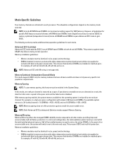
...DIMMs require Advanced ECC mode to each mode. Memory Sparing NOTE: To use x4 device width and does not impose any specific slot population requirements. Memory Mirroring Memory Mirroring offers the strongest DIMM reliability mode compared to all guidelines for sockets with black ... release tabs. The allowable configurations depend on . NOTE: Advanced ECC with white release tabs must be identical and similar rule applies for specific RAS features must be identical in size, speed, and technology. • DIMMs installed in memory optimized (independent channel) mode. The...
...DIMMs require Advanced ECC mode to each mode. Memory Sparing NOTE: To use x4 device width and does not impose any specific slot population requirements. Memory Mirroring Memory Mirroring offers the strongest DIMM reliability mode compared to all guidelines for sockets with black ... release tabs. The allowable configurations depend on . NOTE: Advanced ECC with white release tabs must be identical and similar rule applies for specific RAS features must be identical in size, speed, and technology. • DIMMs installed in memory optimized (independent channel) mode. The...
Owner's Manual
Page 123
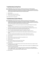
... Memory Module Installation Guidelines. 14. Damage due to resolve the problem. Make any changes to servicing that is not authorized by Dell is not covered by your warranty. You should only perform troubleshooting and simple repairs as authorized in your product documentation, or as... support team. See Using System Diagnostics for available diagnostic tests. Close the system. 10. If a diagnostic test or error message indicates a specific memory module as faulty, swap or replace the module with the product. 1. Damage due to the memory settings, if needed. Read and...
... Memory Module Installation Guidelines. 14. Damage due to resolve the problem. Make any changes to servicing that is not authorized by Dell is not covered by your warranty. You should only perform troubleshooting and simple repairs as authorized in your product documentation, or as... support team. See Using System Diagnostics for available diagnostic tests. Close the system. 10. If a diagnostic test or error message indicates a specific memory module as faulty, swap or replace the module with the product. 1. Damage due to the memory settings, if needed. Read and...

Owner's Manual
Page 135
7 Technical Specifications NOTE: The following specifications apply to both the processors must be installed. (Slot 5) One full-height, full-length x8 link (Slot 6) One full-height, full-length x8 link (PowerEdge R720) (Slot 7) One full-height, full-length x8 link (PowerEdge R720) (Slot 6) One full-height, full-length x16 link Memory Architecture Memory module sockets Memory ...profile x8 link (Slot 3) One half-height, low-profile x8 link (Slot 4) One full-height, full-length x16 link NOTE: To use slots 1 through 4, both PowerEdge R720 and PowerEdge R720xd unless specified otherwise.
7 Technical Specifications NOTE: The following specifications apply to both the processors must be installed. (Slot 5) One full-height, full-length x8 link (Slot 6) One full-height, full-length x8 link (PowerEdge R720) (Slot 7) One full-height, full-length x8 link (PowerEdge R720) (Slot 6) One full-height, full-length x16 link Memory Architecture Memory module sockets Memory ...profile x8 link (Slot 3) One half-height, low-profile x8 link (Slot 4) One full-height, full-length x16 link NOTE: To use slots 1 through 4, both PowerEdge R720 and PowerEdge R720xd unless specified otherwise.

Owner's Manual
Page 138
...°C to 45 °C at 10% to 90% RH with 26 °C max dew point. NOTE: When using PowerEdge R720 with internal GPU card(s), the continuous operation range is 10 °C to 30 °C at 5% to 80% RH, with... • The operating temperature specified is not supported. • Redundant power supplies are required. • Non Dell qualified peripheral cards and/or peripheral cards greater than 25 W are not supported. 138 Environmental NOTE: For additional ...5 °C to 40 °C at 10% to 40 °C for specific system configurations, see dell.com/environmental_datasheets.
...°C to 45 °C at 10% to 90% RH with 26 °C max dew point. NOTE: When using PowerEdge R720 with internal GPU card(s), the continuous operation range is 10 °C to 30 °C at 5% to 80% RH, with... • The operating temperature specified is not supported. • Redundant power supplies are required. • Non Dell qualified peripheral cards and/or peripheral cards greater than 25 W are not supported. 138 Environmental NOTE: For additional ...5 °C to 40 °C at 10% to 40 °C for specific system configurations, see dell.com/environmental_datasheets.
Owner's Manual
Page 143
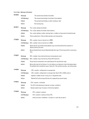
... sink. Check CPU or BIOS revision. If present, re-seat the processor. 143 Details The processor temperature increased beyond the operational range. Review the technical specifications for fan failures. Review system logs for power or thermal exceptions. Check battery. CPU0001 Message CPU has a thermal trip (over-temperature) event. Error Code Message...
... sink. Check CPU or BIOS revision. If present, re-seat the processor. 143 Details The processor temperature increased beyond the operational range. Review the technical specifications for fan failures. Review system logs for power or thermal exceptions. Check battery. CPU0001 Message CPU has a thermal trip (over-temperature) event. Error Code Message...
Technical Guide
Page 3
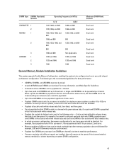
...1 System overview...6 Introduction...6 New technologies ...7 2 System features ...8 Specifications ...8 Comparison of PowerEdge systems ...10 3 Chassis views and features ...11 Chassis views ......Dell OpenManage systems management...44 Systems management solutions ...44 OpenManage systems management ...45 Dell server management operations...49 Appendix A. Additional specifications...52 Chassis dimensions ...52 Chassis weight...52 Power supply specifications ...53 Environmental specifications ...53 Video specifications ...54 Rack rail specifications ...55 USB peripherals ...55 iii PowerEdge R720...
...1 System overview...6 Introduction...6 New technologies ...7 2 System features ...8 Specifications ...8 Comparison of PowerEdge systems ...10 3 Chassis views and features ...11 Chassis views ......Dell OpenManage systems management...44 Systems management solutions ...44 OpenManage systems management ...45 Dell server management operations...49 Appendix A. Additional specifications...52 Chassis dimensions ...52 Chassis weight...52 Power supply specifications ...53 Environmental specifications ...53 Video specifications ...54 Rack rail specifications ...55 USB peripherals ...55 iii PowerEdge R720...

Technical Guide
Page 4
...iDRAC7 Express and Enterprise 46 Table 29. Environmental specifications ...53 Table 33. Industry standard documents ...56 Table 36. Additional resources ...57 Figure 1. R720 front view (2.5" chassis without bezel 12 Figure 5. R720 back view...12 Figure 6. R720 internal chassis view ...13 Figure 8. QRL ... without bezel 11 Figure 3. Rack network daughter card (NDC)...30 iv PowerEdge R720 and R720xd Technical Guide Memory RAS features ...24 Table 11. R720xd LED panel ...15 Figure 11. Power supply specifications ...53 Table 32. R720xd back view...13 Figure 7. Appendix B. Supported...
...iDRAC7 Express and Enterprise 46 Table 29. Environmental specifications ...53 Table 33. Industry standard documents ...56 Table 36. Additional resources ...57 Figure 1. R720 front view (2.5" chassis without bezel 12 Figure 5. R720 back view...12 Figure 6. R720 internal chassis view ...13 Figure 8. QRL ... without bezel 11 Figure 3. Rack network daughter card (NDC)...30 iv PowerEdge R720 and R720xd Technical Guide Memory RAS features ...24 Table 11. R720xd LED panel ...15 Figure 11. Power supply specifications ...53 Table 32. R720xd back view...13 Figure 7. Appendix B. Supported...
Technical Guide
Page 8
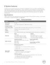
Table 2 lists the technical specifications for the PowerEdge R720 and R720xd systems. For the latest information on supported features, visit Dell.com. R720 only) PERC H310 PERC H710 PERC H710P External HBAs (RAID): PERC H810 External HBAs (non-RAID): 6Gbps SAS HBA R720 drive bay options: Up to 16 x 2.5" Up to 8 x 2.5" + 8 x 2.5" (with dual RAID controllers...
Table 2 lists the technical specifications for the PowerEdge R720 and R720xd systems. For the latest information on supported features, visit Dell.com. R720 only) PERC H310 PERC H710 PERC H710P External HBAs (RAID): PERC H810 External HBAs (non-RAID): 6Gbps SAS HBA R720 drive bay options: Up to 16 x 2.5" Up to 8 x 2.5" + 8 x 2.5" (with dual RAID controllers...
Technical Guide
Page 9
... 2.0 compliant Rack support Operating systems ReadyRails™ sliding rails with 2 x 1GbE (TOE and iSCSI offload available on the specific versions and additions, visit Dell.com/OSsupport. 1GB means 1 billion bytes and TB means 1 trillion bytes; ECC memory, interactive LCD screen (R720 only); extended thermal support; hot-plug redundant fan; luggage-tag; TPM; Feature... supplies; hot-plug drive bays; dual internal SD support; actual capacity varies with preloaded material and operating environment and will be less 2Available Q2 2012 9 PowerEdge R720 and R720xd Technical Guide
... 2.0 compliant Rack support Operating systems ReadyRails™ sliding rails with 2 x 1GbE (TOE and iSCSI offload available on the specific versions and additions, visit Dell.com/OSsupport. 1GB means 1 billion bytes and TB means 1 trillion bytes; ECC memory, interactive LCD screen (R720 only); extended thermal support; hot-plug redundant fan; luggage-tag; TPM; Feature... supplies; hot-plug drive bays; dual internal SD support; actual capacity varies with preloaded material and operating environment and will be less 2Available Q2 2012 9 PowerEdge R720 and R720xd Technical Guide
Technical Guide
Page 16
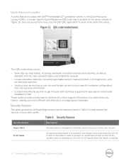
... to learn more efficient and effective in managing your specific hardware configuration info and warranty information Contact Dell directly (by link) to get in touch with Dell™ PowerEdge 12th generation servers is the Quick Resource Locator (QRL)-a model-specific Quick Response (QR) code that is located on ... has the features listed in Figure 11). Security feature Cover latch Front bezel Description A tooled latch is installed. 16 PowerEdge R720 and R720xd Technical Guide System status is viewable on the server (shown in Table 5 to help ensure the security of ...
... to learn more efficient and effective in managing your specific hardware configuration info and warranty information Contact Dell directly (by link) to get in touch with Dell™ PowerEdge 12th generation servers is the Quick Resource Locator (QRL)-a model-specific Quick Response (QR) code that is located on ... has the features listed in Figure 11). Security feature Cover latch Front bezel Description A tooled latch is installed. 16 PowerEdge R720 and R720xd Technical Guide System status is viewable on the server (shown in Table 5 to help ensure the security of ...

