
Getting Started Guide
Page 8
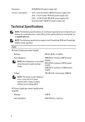
NOTE: The following specifications are only those required by law to support.dell.com. supply) 2891 BTU/hr maximum (750 W power supply) 4100 BTU/hr maximum (1100 W power supply) Voltage 100-240 V AC, autoranging, 50/60 Hz NOTE:...W Heat dissipation 1908 BTU/hr maximum (495 W power NOTE: Heat dissipation is also designed to be connected to IT power systems with a phase to both PowerEdge R720 and PowerEdge R720xd unless specified. Power AC Power Supply (per power supply) (when available) Wattage 1100 W Heat dissipation 4416 BTU/hour maximum 8 For a complete and current listing...
NOTE: The following specifications are only those required by law to support.dell.com. supply) 2891 BTU/hr maximum (750 W power supply) 4100 BTU/hr maximum (1100 W power supply) Voltage 100-240 V AC, autoranging, 50/60 Hz NOTE:...W Heat dissipation 1908 BTU/hr maximum (495 W power NOTE: Heat dissipation is also designed to be connected to IT power systems with a phase to both PowerEdge R720 and PowerEdge R720xd unless specified. Power AC Power Supply (per power supply) (when available) Wattage 1100 W Heat dissipation 4416 BTU/hour maximum 8 For a complete and current listing...
Getting Started Guide
Page 9
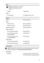
...Without rack latches Depth (includes bezel) Weight (maximum) 2.5-inch hard-drive systems 3.5-inch hard-drive systems (PowerEdge R720) 3.5-inch hard-drive systems (PowerEdge R720xd) Weight (empty) 2.5-inch hard-drive systems 3.5-inch hard-drive systems 87.3 mm (3.44 inch) 482... lbs) 10.3 kg (22.7 lbs) Environmental NOTE: For additional information about environmental measurements for specific system configurations, see dell.com/environmental_datasheets. Power NOTE: Heat dissipation is calculated using the power supply wattage rating. Temperature Operating Continuous operation: 10 °...
...Without rack latches Depth (includes bezel) Weight (maximum) 2.5-inch hard-drive systems 3.5-inch hard-drive systems (PowerEdge R720) 3.5-inch hard-drive systems (PowerEdge R720xd) Weight (empty) 2.5-inch hard-drive systems 3.5-inch hard-drive systems 87.3 mm (3.44 inch) 482... lbs) 10.3 kg (22.7 lbs) Environmental NOTE: For additional information about environmental measurements for specific system configurations, see dell.com/environmental_datasheets. Power NOTE: Heat dissipation is calculated using the power supply wattage rating. Temperature Operating Continuous operation: 10 °...
Owner's Manual
Page 6
... Optional Hard-Drive Backplane (Back 108 Control Panel...109 Removing The Control Panel (PowerEdge R720 109 Installing The Control Panel (PowerEdge R720 111 Removing The Control Panel (PowerEdge R720xd 111 Installing The Control Panel (PowerEdge R720xd 112 Removing The I/O Panel (PowerEdge R720xd 113 Installing The I/O Panel (PowerEdge R720xd 114 System Board...114 Removing The System Board...114 Installing The System Board...116...
... Optional Hard-Drive Backplane (Back 108 Control Panel...109 Removing The Control Panel (PowerEdge R720 109 Installing The Control Panel (PowerEdge R720 111 Removing The Control Panel (PowerEdge R720xd 111 Installing The Control Panel (PowerEdge R720xd 112 Removing The I/O Panel (PowerEdge R720xd 113 Installing The I/O Panel (PowerEdge R720xd 114 System Board...114 Removing The System Board...114 Installing The System Board...116...
Owner's Manual
Page 11
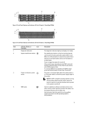
...-compliant operating systems, turning off the system using the end of the buttons is turned off . Front-Panel Features and Indicators (2.5 Inch Chassis)-PowerEdge R720xd Item Indicator, Button, or Icon Description Connector 1 Diagnostic indicators The diagnostic indicators light up to display error status. 2 System identification button The ... indicator on the front and back panels can be used to the system. Front-Panel Features and Indicators (3.5 Inch Chassis)-PowerEdge R720xd Figure 4. Use this button only if directed to the system is pressed again. Figure 3.
...-compliant operating systems, turning off the system using the end of the buttons is turned off . Front-Panel Features and Indicators (2.5 Inch Chassis)-PowerEdge R720xd Item Indicator, Button, or Icon Description Connector 1 Diagnostic indicators The diagnostic indicators light up to display error status. 2 System identification button The ... indicator on the front and back panels can be used to the system. Front-Panel Features and Indicators (3.5 Inch Chassis)-PowerEdge R720xd Figure 4. Use this button only if directed to the system is pressed again. Figure 3.

Owner's Manual
Page 14
... Help. NOTE: No diagnostic indicators are present only on , and in standby, and any video output. The indicator blinks amber if the system is on PowerEdge R720xd. If it into a working power source and press the power button. Corrective Action See the System Event Log to a problem with these indicators: Health indicator...
... Help. NOTE: No diagnostic indicators are present only on , and in standby, and any video output. The indicator blinks amber if the system is on PowerEdge R720xd. If it into a working power source and press the power button. Corrective Action See the System Event Log to a problem with these indicators: Health indicator...

Owner's Manual
Page 17
Back-Panel Features and Indicators-PowerEdge R720xd Item Indicator, Button, or Icon Description Connector 1 System identification button The identification buttons on and off. NOTE: The port is available for use only if ... connector Allows you to connect a VGA display to the system. 7 USB connectors (2) 8 Ethernet connectors Allows you to connect up to locate a particular system within a rack. PowerEdge R720 PowerEdge R720xd When one of these buttons is pressed, the system status indicator on the back flashes until one of the buttons is pressed again. Figure 8. When...
Back-Panel Features and Indicators-PowerEdge R720xd Item Indicator, Button, or Icon Description Connector 1 System identification button The identification buttons on and off. NOTE: The port is available for use only if ... connector Allows you to connect a VGA display to the system. 7 USB connectors (2) 8 Ethernet connectors Allows you to connect up to locate a particular system within a rack. PowerEdge R720 PowerEdge R720xd When one of these buttons is pressed, the system status indicator on the back flashes until one of the buttons is pressed again. Figure 8. When...
Owner's Manual
Page 18
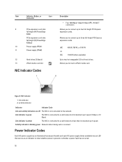
... less than its maximum port speed (1 Gbps or 10 Gbps). Item Indicator, Button, or Icon Connector 9 PCIe expansion card slots full height (4) (PowerEdge R720) PCIe expansion card slots full height (3) (PowerEdge R720xd) 10 Power supply (PSU1) 11 Power supply (PSU2) 12 Hard drives (2) (back) 13 vFlash media card slot NIC Indicator Codes Description •...
... less than its maximum port speed (1 Gbps or 10 Gbps). Item Indicator, Button, or Icon Connector 9 PCIe expansion card slots full height (4) (PowerEdge R720) PCIe expansion card slots full height (3) (PowerEdge R720xd) 10 Power supply (PSU1) 11 Power supply (PSU2) 12 Hard drives (2) (back) 13 vFlash media card slot NIC Indicator Codes Description •...
Owner's Manual
Page 23
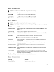
.... Menu Item System Information Memory Settings Processor Settings SATA Settings Description Displays information about the system such as speed, cache size, and so on the PowerEdge R720xd. Integrated Devices Displays options to enable or disable integrated device controllers and ports, and to enable or disable the integrated SATA controller and ports. Menu...
.... Menu Item System Information Memory Settings Processor Settings SATA Settings Description Displays information about the system such as speed, cache size, and so on the PowerEdge R720xd. Integrated Devices Displays options to enable or disable integrated device controllers and ports, and to enable or disable the integrated SATA controller and ports. Menu...

Owner's Manual
Page 39
... the safety instructions that is not authorized by Dell is not covered by your system with the product. CAUTION: Never operate your warranty. network daughter card Cooling Shroud 9. Damage due to servicing that came with the cooling shroud removed. Figure 15. Inside the System-PowerEdge R720xd 1. vFlash media slot 6. The system may only...
... the safety instructions that is not authorized by Dell is not covered by your system with the product. CAUTION: Never operate your warranty. network daughter card Cooling Shroud 9. Damage due to servicing that came with the cooling shroud removed. Figure 15. Inside the System-PowerEdge R720xd 1. vFlash media slot 6. The system may only...
Owner's Manual
Page 41
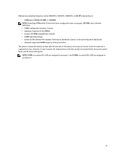
Memory bus operating frequency can be 1600 MT/s, 1333 MT/s, 1066 MT/s, or 800 MT/s depending on: • DIMM type (UDIMM, RDIMM, or LRDIMM) NOTE: PowerEdge R720xd with 3.5 inch hard-drive configuration does not support LRDIMMs due to thermal limitations. • DIMM configuration (number of ranks) • maximum frequency of the DIMMs &#...
Memory bus operating frequency can be 1600 MT/s, 1333 MT/s, 1066 MT/s, or 800 MT/s depending on: • DIMM type (UDIMM, RDIMM, or LRDIMM) NOTE: PowerEdge R720xd with 3.5 inch hard-drive configuration does not support LRDIMMs due to thermal limitations. • DIMM configuration (number of ranks) • maximum frequency of the DIMMs &#...
Owner's Manual
Page 50
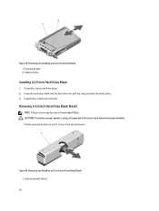
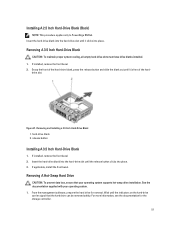
...-drive slots must have drive blanks installed. If installed, remove the front bezel. 2. Removing A 2.5 Inch Hard-Drive Blank (Back) NOTE: This procedure applies only to PowerEdge R720xd. If applicable, install the front bezel.
...-drive slots must have drive blanks installed. If installed, remove the front bezel. 2. Removing A 2.5 Inch Hard-Drive Blank (Back) NOTE: This procedure applies only to PowerEdge R720xd. If applicable, install the front bezel.
Owner's Manual
Page 51
.... 1. From the management software, prepare the hard drive for the storage controller. 51 Installing A 2.5 Inch Hard-Drive Blank (Back) NOTE: This procedure applies only to PowerEdge R720xd. Figure 21. Removing A Hot-Swap Hard Drive CAUTION: To prevent data loss, ensure that the hard drive can be removed safely. Removing A 3.5 Inch Hard-Drive...
.... 1. From the management software, prepare the hard drive for the storage controller. 51 Installing A 2.5 Inch Hard-Drive Blank (Back) NOTE: This procedure applies only to PowerEdge R720xd. Figure 21. Removing A Hot-Swap Hard Drive CAUTION: To prevent data loss, ensure that the hard drive can be removed safely. Removing A 3.5 Inch Hard-Drive...
Owner's Manual
Page 63
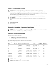
... turn the system on the riser, both the processors must be done by the online or telephone service and support team. NOTE: PowerEdge R720xd does not support riser 3 (default). 63 Open the system. 3. Place all cables to servicing that came with the product. 1....and follow the safety instructions that is not authorized by Dell is displayed. It does not prevent your warranty. Damage due to be routed in your system configuration: • PowerEdge R720 supports seven expansion cards • PowerEdge R720xd supports six expansion cards The following PCI Express Generation 3...
... turn the system on the riser, both the processors must be done by the online or telephone service and support team. NOTE: PowerEdge R720xd does not support riser 3 (default). 63 Open the system. 3. Place all cables to servicing that came with the product. 1....and follow the safety instructions that is not authorized by Dell is displayed. It does not prevent your warranty. Damage due to be routed in your system configuration: • PowerEdge R720 supports seven expansion cards • PowerEdge R720xd supports six expansion cards The following PCI Express Generation 3...
Owner's Manual
Page 72
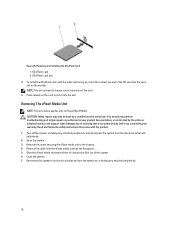
... safety instructions that is not authorized by Dell is keyed to its electrical outlet and turn the system on the module. Close the system. 7. Removing The vFlash Media Unit NOTE: This procedure applies only to the chassis. 4. Figure 39. Remove the screw securing the vFlash media unit to PowerEdge R720xd. SD vFlash card 2.
... safety instructions that is not authorized by Dell is keyed to its electrical outlet and turn the system on the module. Close the system. 7. Removing The vFlash Media Unit NOTE: This procedure applies only to the chassis. 4. Figure 39. Remove the screw securing the vFlash media unit to PowerEdge R720xd. SD vFlash card 2.
Owner's Manual
Page 73
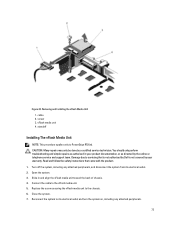
...the cable to the chassis. 6. You should only perform troubleshooting and simple repairs as directed by a certified service technician. Reconnect the system to PowerEdge R720xd. Removing and Installing the vFlash Media Unit 1. Figure 40. CAUTION: Many repairs may only be done by the online or telephone service and ...vFlash media unit to the vFlash media unit. 5. vFlash media unit 4. Read and follow the safety instructions that is not authorized by Dell is not covered by your product documentation, or as authorized in and align the vFlash media unit toward the back of chassis. 4....
...the cable to the chassis. 6. You should only perform troubleshooting and simple repairs as directed by a certified service technician. Reconnect the system to PowerEdge R720xd. Removing and Installing the vFlash Media Unit 1. Figure 40. CAUTION: Many repairs may only be done by the online or telephone service and ...vFlash media unit to the vFlash media unit. 5. vFlash media unit 4. Read and follow the safety instructions that is not authorized by Dell is not covered by your product documentation, or as authorized in and align the vFlash media unit toward the back of chassis. 4....
Owner's Manual
Page 93
...and temporarily label them in your warranty. Open the system. Read and follow the safety instructions that is not authorized by Dell is not covered by your product documentation, or as authorized in the same locations. 4. If installed, remove the front ... the 3.5 Inch (x8) SAS/SATA Backplane-PowerEdge R720 1. Turn off the system, including any attached peripherals, and disconnect the system from the backplane. 8. Remove all hard drives. 7. Figure 53. 3.5 inch (x8) SAS/SATA backplane or no backplane PowerEdge R720xd 2.5 inch (x24) SAS/SATA backplane and optional...
...and temporarily label them in your warranty. Open the system. Read and follow the safety instructions that is not authorized by Dell is not covered by your product documentation, or as authorized in the same locations. 4. If installed, remove the front ... the 3.5 Inch (x8) SAS/SATA Backplane-PowerEdge R720 1. Turn off the system, including any attached peripherals, and disconnect the system from the backplane. 8. Remove all hard drives. 7. Figure 53. 3.5 inch (x8) SAS/SATA backplane or no backplane PowerEdge R720xd 2.5 inch (x24) SAS/SATA backplane and optional...

Owner's Manual
Page 102
left control panel cable 4. power cable B 9. front I/O cable 10. I2C cable 5. Removing and Installing the 3.5 Inch (x12) SAS/SATA Backplane-PowerEdge R720xd 1. power cable A 6. hard-drive backplane connectors (12) 102 release tabs (2) 2. right control panel cable 11. Figure 62. SAS cables (3) 8. pass-through I2C cable 3. USB cable 7. x12 hard-drive backplane 12.
left control panel cable 4. power cable B 9. front I/O cable 10. I2C cable 5. Removing and Installing the 3.5 Inch (x12) SAS/SATA Backplane-PowerEdge R720xd 1. power cable A 6. hard-drive backplane connectors (12) 102 release tabs (2) 2. right control panel cable 11. Figure 62. SAS cables (3) 8. pass-through I2C cable 3. USB cable 7. x12 hard-drive backplane 12.
Owner's Manual
Page 103
system board 3. SAS backplane 103 cable retention bracket 2. Figure 63. integrated storage controller card 4. SAS connector on the system board 5. Cabling Diagram-3.5 Iinch (x12) SAS/SATA Backplane-PowerEdge R720xd 1.
system board 3. SAS backplane 103 cable retention bracket 2. Figure 63. integrated storage controller card 4. SAS connector on the system board 5. Cabling Diagram-3.5 Iinch (x12) SAS/SATA Backplane-PowerEdge R720xd 1.
Owner's Manual
Page 104
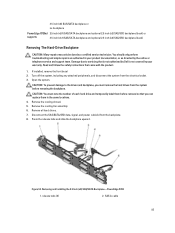
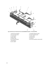
x24 hard-drive backplane 2. left control panel cable 3. release tabs (2) 4. pass-through I2C cable 7. right control panel cable 11. front I/O cable 13. power cable A 5. power cable B 9. power cable C 12. USB cable 14. sideband cable 6. SAS cables (3) 8. Figure 64. backplane/expander bracket 10. Removing and Installing the 2.5 Inch (x24) SAS/SATA Backplane-PowerEdge R720xd 1. hard-drive backplane connectors (24) 104
x24 hard-drive backplane 2. left control panel cable 3. release tabs (2) 4. pass-through I2C cable 7. right control panel cable 11. front I/O cable 13. power cable A 5. power cable B 9. power cable C 12. USB cable 14. sideband cable 6. SAS cables (3) 8. Figure 64. backplane/expander bracket 10. Removing and Installing the 2.5 Inch (x24) SAS/SATA Backplane-PowerEdge R720xd 1. hard-drive backplane connectors (24) 104
Owner's Manual
Page 105
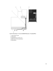
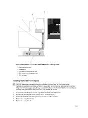
..., and power cable(s) to align the hard-drive backplane. 2. Cabling Diagram-2.5 Inch (x24) SAS/SATA Backplane-PowerEdge R720xd 1. SAS connector on the system board 5. Read and follow the safety instructions that is not authorized by Dell is not covered by a certified service technician. Replace the cooling-fan assembly. 5. Use the hooks at the...
..., and power cable(s) to align the hard-drive backplane. 2. Cabling Diagram-2.5 Inch (x24) SAS/SATA Backplane-PowerEdge R720xd 1. SAS connector on the system board 5. Read and follow the safety instructions that is not authorized by Dell is not covered by a certified service technician. Replace the cooling-fan assembly. 5. Use the hooks at the...


