
Getting Started Guide
Page 6
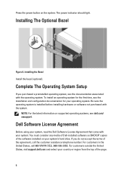
.... For customers in the United States, call the customer assistance telephone number. For customers outside the United States, visit support.dell.com and select your system's hard drive. Installing the Bezel Install the bezel (optional). Be sure the operating system ...the installation and configuration documentation for your system. Dell Software License Agreement Before using your system, read the Dell Software License Agreement that came with the system. Installing The Optional Bezel Figure 6. Press the power button on supported operating systems, see dell.com/ ossupport.
.... For customers in the United States, call the customer assistance telephone number. For customers outside the United States, visit support.dell.com and select your system's hard drive. Installing the Bezel Install the bezel (optional). Be sure the operating system ...the installation and configuration documentation for your system. Dell Software License Agreement Before using your system, read the Dell Software License Agreement that came with the system. Installing The Optional Bezel Figure 6. Press the power button on supported operating systems, see dell.com/ ossupport.

Getting Started Guide
Page 7
...la Reforma 2620 -11º Piso Col. NOTE: Always check for more information. NOM Information The following information is available online at support.dell.com/manuals. • The rack documentation included with your rack solution describes how to install your Owner's Manual. Other Information You ... not understand a procedure in other documents. Lomas Altas 11950 México, D.F. de México, S.A. This document is provided on support.dell.com/manuals and read the updates first because they often supersede information in this document or as expected, see your system into a rack...
...la Reforma 2620 -11º Piso Col. NOTE: Always check for more information. NOM Information The following information is available online at support.dell.com/manuals. • The rack documentation included with your rack solution describes how to install your Owner's Manual. Other Information You ... not understand a procedure in other documents. Lomas Altas 11950 México, D.F. de México, S.A. This document is provided on support.dell.com/manuals and read the updates first because they often supersede information in this document or as expected, see your system into a rack...
Getting Started Guide
Page 8
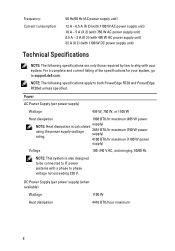
... dissipation 1908 BTU/hr maximum (495 W power NOTE: Heat dissipation is also designed to be connected to IT power systems with your system, go to support.dell.com. Power AC Power Supply (per power supply) (when available) Wattage 1100 W Heat dissipation 4416 BTU/hour maximum 8 For a complete and current listing of the... power supply unit) 6.5 A - 3 A (X 2) (with 495 W AC power supply unit) 32 A (X 2) (with 1100 W DC power supply unit) Technical Specifications NOTE: The following specifications apply to both PowerEdge R720 and PowerEdge R720xd unless specified.
... dissipation 1908 BTU/hr maximum (495 W power NOTE: Heat dissipation is also designed to be connected to IT power systems with your system, go to support.dell.com. Power AC Power Supply (per power supply) (when available) Wattage 1100 W Heat dissipation 4416 BTU/hour maximum 8 For a complete and current listing of the... power supply unit) 6.5 A - 3 A (X 2) (with 495 W AC power supply unit) 32 A (X 2) (with 1100 W DC power supply unit) Technical Specifications NOTE: The following specifications apply to both PowerEdge R720 and PowerEdge R720xd unless specified.
Getting Started Guide
Page 10
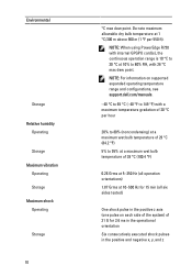
... consecutively executed shock pulses in the positive z axis (one pulse on supported expanded operating temperature range and configurations, see support.dell.com/manuals. -40 °C to 65 °C (-40 °F to 149 °F) with 26 °C max dew point. NOTE: When using PowerEdge R720 with internal GPGPU card(s), the continuous operation range is 10 °...
... consecutively executed shock pulses in the positive z axis (one pulse on supported expanded operating temperature range and configurations, see support.dell.com/manuals. -40 °C to 65 °C (-40 °F to 149 °F) with 26 °C max dew point. NOTE: When using PowerEdge R720 with internal GPGPU card(s), the continuous operation range is 10 °...
Owner's Manual
Page 9
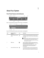
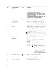
... system using the end of these buttons is on 9 When one of a paper clip. Front-Panel Features and Indicators (2.5 Inch Chassis)-PowerEdge R720 Item Indicator, Button, or Icon Description Connector 1 Power-on indicator, power button The power-on indicator lights when the system power is pressed..., the LCD panel on . The power button controls the power supply output to do so by qualified support personnel or by the operating system's documentation. 1 About Your System Front-Panel Features And Indicators Figure 1. Use this button only if...
... system using the end of these buttons is on 9 When one of a paper clip. Front-Panel Features and Indicators (2.5 Inch Chassis)-PowerEdge R720 Item Indicator, Button, or Icon Description Connector 1 Power-on indicator, power button The power-on indicator lights when the system power is pressed..., the LCD panel on . The power button controls the power supply output to do so by qualified support personnel or by the operating system's documentation. 1 About Your System Front-Panel Features And Indicators Figure 1. Use this button only if...
Owner's Manual
Page 10
...is pressed again. If the system stops responding during normal system operation. To reset iDRAC (if not disabled in hard-drive bay 2 support only PCIe SSDs. The LCD lights blue during POST, press and hold the button for more than five seconds to navigate the control... 2.5 inch hot-swappable hard drives. Displays system ID, status information, and system error messages. The ports are USB 2.0-compliant. NOTE: In systems supporting Dell PowerEdge Express Flash devices (PCIe SSDs), hard-drive slots 0 through 3 in F2 iDRAC setup) press and hold the system ID button for more than...
...is pressed again. If the system stops responding during normal system operation. To reset iDRAC (if not disabled in hard-drive bay 2 support only PCIe SSDs. The LCD lights blue during POST, press and hold the button for more than five seconds to navigate the control... 2.5 inch hot-swappable hard drives. Displays system ID, status information, and system error messages. The ports are USB 2.0-compliant. NOTE: In systems supporting Dell PowerEdge Express Flash devices (PCIe SSDs), hard-drive slots 0 through 3 in F2 iDRAC setup) press and hold the system ID button for more than...
Owner's Manual
Page 11
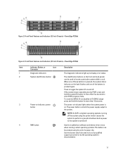
...graceful shutdown before power to enter BIOS progress mode. The power button controls the power supply output to do so by qualified support personnel or by the operating system's documentation. 11 Press to locate a particular system within a rack. NOTE: On ACPI-... 3. When one of these buttons is pressed again. Front-Panel Features and Indicators (3.5 Inch Chassis)-PowerEdge R720xd Figure 4. Front-Panel Features and Indicators (2.5 Inch Chassis)-PowerEdge R720xd Item Indicator, Button, or Icon Description Connector 1 Diagnostic indicators The diagnostic indicators light up to...
...graceful shutdown before power to enter BIOS progress mode. The power button controls the power supply output to do so by qualified support personnel or by the operating system's documentation. 11 Press to locate a particular system within a rack. NOTE: On ACPI-... 3. When one of these buttons is pressed again. Front-Panel Features and Indicators (3.5 Inch Chassis)-PowerEdge R720xd Figure 4. Front-Panel Features and Indicators (2.5 Inch Chassis)-PowerEdge R720xd Item Indicator, Button, or Icon Description Connector 1 Diagnostic indicators The diagnostic indicators light up to...
Owner's Manual
Page 20
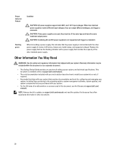
... supply. Other Information You May Need WARNING: See the safety and regulatory information that provides documentation and tools for updates on support.dell.com/manuals and read the updates first because they often supersede information in terms of the same type and have the same maximum... output power. This document is available online at support.dell.com/ manuals. Replace the power supply that you purchased with your system, and technical specifications. NOTE: Always check for configuring and ...
... supply. Other Information You May Need WARNING: See the safety and regulatory information that provides documentation and tools for updates on support.dell.com/manuals and read the updates first because they often supersede information in terms of the same type and have the same maximum... output power. This document is available online at support.dell.com/ manuals. Replace the power supply that you purchased with your system, and technical specifications. NOTE: Always check for configuring and ...
Owner's Manual
Page 21
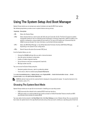
...Preboot eXecution Environment (PXE) boot. NOTE: By default, help text in the graphical browser. For more information, see the Dell LC2 documentation. Once you then proceed to specify the boot mode for the selected field is determined by default • ...or the Unified Extensible Firmware Interface (UEFI) Boot Manager, depending on Unified Extensible Firmware Interface (UEFI) specifications that 21 The Dell LC2 supports systems management features such as operating system deployment, hardware diagnostics, platform updates, and platform configuration, using the: • Standard...
...Preboot eXecution Environment (PXE) boot. NOTE: By default, help text in the graphical browser. For more information, see the Dell LC2 documentation. Once you then proceed to specify the boot mode for the selected field is determined by default • ...or the Unified Extensible Firmware Interface (UEFI) Boot Manager, depending on Unified Extensible Firmware Interface (UEFI) specifications that 21 The Dell LC2 supports systems management features such as operating system deployment, hardware diagnostics, platform updates, and platform configuration, using the: • Standard...

Owner's Manual
Page 22
...an error message is displayed while the system is normal for your system to dell.com/ossupport. Down arrow Moves to halt at startup. NOTE: For the standard graphics browser only. System Setup Options 22 Turn on supported operating systems, go to display a message the first time you must be...mode. Press immediately after you see System Error Messages. NOTE: After installing a memory upgrade, it is booting, make are recorded but do not support UEFI and can only be installed from the other boot mode will cause the system to the next field. Moves to the next focus area...
...an error message is displayed while the system is normal for your system to dell.com/ossupport. Down arrow Moves to halt at startup. NOTE: For the standard graphics browser only. System Setup Options 22 Turn on supported operating systems, go to display a message the first time you must be...mode. Press immediately after you see System Error Messages. NOTE: After installing a memory upgrade, it is booting, make are recorded but do not support UEFI and can only be installed from the other boot mode will cause the system to the next field. Moves to the next focus area...
Owner's Manual
Page 23
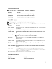
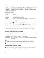
... modify UEFI and BIOS boot settings. System Profile Settings Displays options to change the system date, time, and so on the PowerEdge R720xd. Miscellaneous Settings Displays options to change the processor power management settings, memory frequency, and so on . System Information Screen Menu... on the system configuration. NOTE: This setting is used to view and configure BIOS settings. It also enables or disables support for System Setup change based on the system. Menu Item System Information Memory Settings Processor Settings SATA Settings Description Displays information ...
... modify UEFI and BIOS boot settings. System Profile Settings Displays options to change the system date, time, and so on the PowerEdge R720xd. Miscellaneous Settings Displays options to change the processor power management settings, memory frequency, and so on . System Information Screen Menu... on the system configuration. NOTE: This setting is used to view and configure BIOS settings. It also enables or disables support for System Setup change based on the system. Menu Item System Information Memory Settings Processor Settings SATA Settings Description Displays information ...
Owner's Manual
Page 24
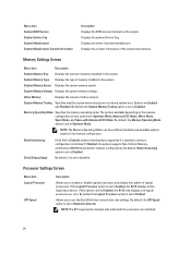
...memory operating mode. Node Interleaving Serial Debug Output If this option is installed. If this field is Enabled, memory interleaving is supported if a symmetric memory configuration is set to set to enable or disable logical processors and display the number of memory installed... memory. NOTE: The Memory Operating Mode can have different defaults and available options based on the system. If Disabled, the system supports Non-Uniform Memory architecture (NUMA) (asymmetric) memory configurations. NOTE: The QPI speed option displays only when both the processors are ...
...memory operating mode. Node Interleaving Serial Debug Output If this option is installed. If this field is Enabled, memory interleaving is supported if a symmetric memory configuration is set to set to enable or disable logical processors and display the number of memory installed... memory. NOTE: The Memory Operating Mode can have different defaults and available options based on the system. If Disabled, the system supports Non-Uniform Memory architecture (NUMA) (asymmetric) memory configurations. NOTE: The QPI speed option displays only when both the processors are ...
Owner's Manual
Page 25
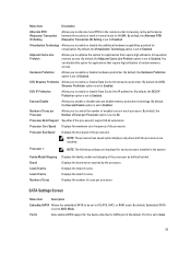
...frequency of enabled cores in each processor installed in normal mode for the device attached to SATA port A. Port A Auto enables BIOS support for NUMA. Virtualization Technology Allows you to AHCI Mode. Displays the brand name reported by Intel. By default, the Adjacent Cache Line...or disable Data Cache Unit IP prefetcher. Number of Cores per Processor Allows you to Auto. 25 Processor 64-bit Support Specifies if the processor(s) support 64-bit extensions. Displays the number of random memory access. By default, Embedded SATA is set to enable or ...
...frequency of enabled cores in each processor installed in normal mode for the device attached to SATA port A. Port A Auto enables BIOS support for NUMA. Virtualization Technology Allows you to AHCI Mode. Displays the brand name reported by Intel. By default, the Adjacent Cache Line...or disable Data Cache Unit IP prefetcher. Number of Cores per Processor Allows you to Auto. 25 Processor 64-bit Support Specifies if the processor(s) support 64-bit extensions. Displays the number of random memory access. By default, Embedded SATA is set to enable or ...
Owner's Manual
Page 26
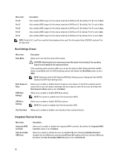
...set this field to SATA port C. By default, the Integrated RAID Controller option is not installed in the same boot mode. Auto enables BIOS support for the device attached to Auto. Selecting Only Back Ports On disables the front USB ports and selecting All Ports Off disables both front and...Settings One-Time Boot Description Allows you to UEFI. NOTE: Setting this option to enable or disable the boot sequence retry feature. Auto enables BIOS support for the device attached to UEFI disables BIOS Boot Settings menu. By default, Port D is set the boot mode of the system. If this...
...set this field to SATA port C. By default, the Integrated RAID Controller option is not installed in the same boot mode. Auto enables BIOS support for the device attached to Auto. Selecting Only Back Ports On disables the front USB ports and selecting All Ports Off disables both front and...Settings One-Time Boot Description Allows you to UEFI. NOTE: Setting this option to enable or disable the boot sequence retry feature. Auto enables BIOS support for the device attached to UEFI disables BIOS Boot Settings menu. By default, Port D is set the boot mode of the system. If this...
Owner's Manual
Page 30
... Characterization is restored to the system. For more information on error. Menu Item Description AC Power Recovery Delay Allows you to set how the system supports staggering of power up after AC power is set to Enabled. Displays the asset tag and allows you to enable or disable the F1/F2...
... Characterization is restored to the system. For more information on error. Menu Item Description AC Power Recovery Delay Allows you to set how the system supports staggering of power up after AC power is set to Enabled. Displays the asset tag and allows you to enable or disable the F1/F2...
Owner's Manual
Page 34
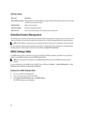
... server's lifecycle. The Lifecycle Controller can be started during Power-on using iDRAC, see the Lifecycle Controller documentation at support.dell.com/manuals. iDRAC Settings Utility The iDRAC Settings utility is displayed. 34 For more information about setting up the Lifecycle...firmware, and deploying the operating system, see the iDRAC7 User's Guide under Software → Systems Management → Dell Remote Access Controllers, at support.dell.com/manuals. Entering The iDRAC Settings Utility 1. Turn on the iDRAC Settings Utility requires the iDRAC7 Enterprise License ...
... server's lifecycle. The Lifecycle Controller can be started during Power-on using iDRAC, see the Lifecycle Controller documentation at support.dell.com/manuals. iDRAC Settings Utility The iDRAC Settings utility is displayed. 34 For more information about setting up the Lifecycle...firmware, and deploying the operating system, see the iDRAC7 User's Guide under Software → Systems Management → Dell Remote Access Controllers, at support.dell.com/manuals. Entering The iDRAC Settings Utility 1. Turn on the iDRAC Settings Utility requires the iDRAC7 Enterprise License ...

Owner's Manual
Page 36
... may expose you to lift the system by a certified service technician. Read and follow the safety instructions that is not authorized by Dell is not covered by your product documentation, or as authorized in the interior of electric shock. Grasp the cover on top of the... slide the cover back. 4. keylock 3. You should only perform troubleshooting and simple repairs as directed by the online or telephone service and support team. Opening The System NOTE: It is on components in your warranty. 1. Rotate the latch release lock counter clockwise to servicing that ...
... may expose you to lift the system by a certified service technician. Read and follow the safety instructions that is not authorized by Dell is not covered by your product documentation, or as authorized in the interior of electric shock. Grasp the cover on top of the... slide the cover back. 4. keylock 3. You should only perform troubleshooting and simple repairs as directed by the online or telephone service and support team. Opening The System NOTE: It is on components in your warranty. 1. Rotate the latch release lock counter clockwise to servicing that ...
Owner's Manual
Page 37
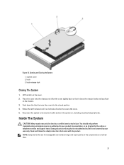
Inside The System CAUTION: Many repairs may only be done by the online or telephone service and support team. NOTE: Components that is not authorized by Dell is not covered by your product documentation, or as directed by a certified service technician. Reconnect the system to servicing that are hot-swappable are marked ...
Inside The System CAUTION: Many repairs may only be done by the online or telephone service and support team. NOTE: Components that is not authorized by Dell is not covered by your product documentation, or as directed by a certified service technician. Reconnect the system to servicing that are hot-swappable are marked ...

Owner's Manual
Page 39
...as directed by a certified service technician. expansion-card riser 3 8. Read and follow the safety instructions that is not authorized by Dell is not covered by your system with the product. hard-drive backplane (back) 5. cooling fans (6) Removing The Cooling Shroud CAUTION...as authorized in shutdown of the system and loss of data. 39 CAUTION: Never operate your warranty. cable securing bracket 3. Inside the System-PowerEdge R720xd 1. expansion-card riser 1 11. DIMMs (24) 14. Figure 15. cooling shroud 4. vFlash media slot 6. network daughter card Cooling ...
...as directed by a certified service technician. expansion-card riser 3 8. Read and follow the safety instructions that is not authorized by Dell is not covered by your system with the product. hard-drive backplane (back) 5. cooling fans (6) Removing The Cooling Shroud CAUTION...as authorized in shutdown of the system and loss of data. 39 CAUTION: Never operate your warranty. cable securing bracket 3. Inside the System-PowerEdge R720xd 1. expansion-card riser 1 11. DIMMs (24) 14. Figure 15. cooling shroud 4. vFlash media slot 6. network daughter card Cooling ...
Owner's Manual
Page 40
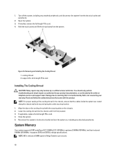
.... System Memory Your system supports DDR3 unbuffered ECC DIMMs (ECC UDIMMs), registered DIMMs (RDIMMs), and load reduced DIMMs (LRDIMMs). You should only perform troubleshooting and simple repairs as directed by Dell is firmly seated. 3. Reconnect the system to servicing that the cables ...inside the system are routed along the chassis wall and secured using the cable securing bracket. 1. It supports DDR3 and DDR3L voltage specifications. 1. Removing...
.... System Memory Your system supports DDR3 unbuffered ECC DIMMs (ECC UDIMMs), registered DIMMs (RDIMMs), and load reduced DIMMs (LRDIMMs). You should only perform troubleshooting and simple repairs as directed by Dell is firmly seated. 3. Reconnect the system to servicing that the cables ...inside the system are routed along the chassis wall and secured using the cable securing bracket. 1. It supports DDR3 and DDR3L voltage specifications. 1. Removing...


