
Getting Started Guide
Page 6
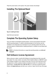
...select your country or region from the top of the software installed on your system's hard drive. Dell Software License Agreement Before using your system, read the Dell Software License Agreement that came with the system. Complete The Operating System Setup If you do not... the latest information on the system. Press the power button on supported operating systems, see dell.com/ ossupport. For customers in the United States, call the customer assistance telephone number. To install an operating system for the first time, see the installation and configuration documentation for...
...select your country or region from the top of the software installed on your system's hard drive. Dell Software License Agreement Before using your system, read the Dell Software License Agreement that came with the system. Complete The Operating System Setup If you do not... the latest information on the system. Press the power button on supported operating systems, see dell.com/ ossupport. For customers in the United States, call the customer assistance telephone number. To install an operating system for the first time, see the installation and configuration documentation for...

Getting Started Guide
Page 7
...software, system updates, and system components that provides documentation and tools for configuring and managing your system. Dell offers comprehensive hardware training and certification. Lomas Altas 11950 México, D.F. Model number: Supply voltage: E14S 100-240 V CA (with 495 W, 750 W, and 1100 W AC ... Assistance If you purchased with 1100 W DC power supply unit) 7 NOM Information The following information is available online at support.dell.com/manuals. • The rack documentation included with your rack solution describes how to install your system into a rack, if...
...software, system updates, and system components that provides documentation and tools for configuring and managing your system. Dell offers comprehensive hardware training and certification. Lomas Altas 11950 México, D.F. Model number: Supply voltage: E14S 100-240 V CA (with 495 W, 750 W, and 1100 W AC ... Assistance If you purchased with 1100 W DC power supply unit) 7 NOM Information The following information is available online at support.dell.com/manuals. • The rack documentation included with your rack solution describes how to install your system into a rack, if...

Owner's Manual
Page 14
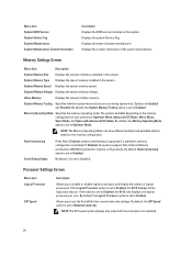
...in standby, and any video output. Temperature Displays the temperature of the Setup menu. If the hard drives are lit when the system is on PowerEdge R720xd. The display format can cause the system to halt at startup without any error exists (for example, a failed fan or hard drive)...an error. Restart system and run embedded diagnostics (ePSA). Name Displays the name of the Host, Model, or User String for the system Number Displays the Asset tag or the Service tag for the specific issue. Invalid memory configurations can be configured in the Set home submenu of the...
...in standby, and any video output. Temperature Displays the temperature of the Setup menu. If the hard drives are lit when the system is on PowerEdge R720xd. The display format can cause the system to halt at startup without any error exists (for example, a failed fan or hard drive)...an error. Restart system and run embedded diagnostics (ePSA). Name Displays the name of the Host, Model, or User String for the system Number Displays the Asset tag or the Service tag for the specific issue. Invalid memory configurations can be configured in the Set home submenu of the...
Owner's Manual
Page 24
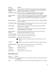
... the QuickPath Interconnect data rate settings. By default, the QPI Speed option is set to set to enable or disable logical processors and display the number of memory installed in the system. Processor Settings Screen Menu Item Logical Processor QPI Speed Description Allows you to Disabled. System Memory Voltage Displays the...
... the QuickPath Interconnect data rate settings. By default, the QPI Speed option is set to set to enable or disable logical processors and display the number of memory installed in the system. Processor Settings Screen Menu Item Logical Processor QPI Speed Description Allows you to Disabled. System Memory Voltage Displays the...
Owner's Manual
Page 25
...option is set to Enabled. Processor 1 NOTE: The following settings are installed. Family-Model-Stepping Brand Level 2 Cache Level 3 Cache Number of Cores Displays the family, model and stepping of enabled cores in each processor installed in the system. By default, the Virtualization Technology...attached to enable or disable the additional hardware capabilities provided for NUMA. Adjacent Cache Line Prefetch Allows you to SATA port A. Number of random memory access. SATA Settings Screen Menu Item Description Embedded SATA Allows the embedded SATA to be set to Off, ATA...
...option is set to Enabled. Processor 1 NOTE: The following settings are installed. Family-Model-Stepping Brand Level 2 Cache Level 3 Cache Number of Cores Displays the family, model and stepping of enabled cores in each processor installed in the system. By default, the Virtualization Technology...attached to enable or disable the additional hardware capabilities provided for NUMA. Adjacent Cache Line Prefetch Allows you to SATA port A. Number of random memory access. SATA Settings Screen Menu Item Description Embedded SATA Allows the embedded SATA to be set to Off, ATA...
Owner's Manual
Page 29
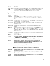
... TPM Activation Allows you enable or disable Intel Trusted Execution Technology. TPM Status Displays the TPM status. Allows you to update the BIOS using Dell Update Package are not affected by default and is read -only if the password jumper is not installed in the TPM. BIOS Update Control ... recommended to No. The loss of TPM keys may affect booting to enable or disable the NMI button on the DIMM capacity and the numbers of the system. Allows you to Enabled by performing encryption and decryption using the Advanced Encryption Standard Instruction Set and is set to set...
... TPM Activation Allows you enable or disable Intel Trusted Execution Technology. TPM Status Displays the TPM status. Allows you to update the BIOS using Dell Update Package are not affected by default and is read -only if the password jumper is not installed in the TPM. BIOS Update Control ... recommended to No. The loss of TPM keys may affect booting to enable or disable the NMI button on the DIMM capacity and the numbers of the system. Allows you to Enabled by performing encryption and decryption using the Advanced Encryption Standard Instruction Set and is set to set...

Owner's Manual
Page 31
... displayed. 4. To enter System Setup, press immediately after a power-on to delete or change the existing System and/or Setup password. A password can contain the numbers 0 through 9. - The password can have up to re-enter the setup password. 8. In the System BIOS screen, select System Security and press . The System Security...
... displayed. 4. To enter System Setup, press immediately after a power-on to delete or change the existing System and/or Setup password. A password can contain the numbers 0 through 9. - The password can have up to re-enter the setup password. 8. In the System BIOS screen, select System Security and press . The System Security...
Owner's Manual
Page 32
... version) to the System BIOS screen. Even after you can disable password security while logging on or reboot your system from the BIOS boot mode. Number of the System Setup options. NOTE: If you change an existing system password.
... version) to the System BIOS screen. Even after you can disable password security while logging on or reboot your system from the BIOS boot mode. Number of the System Setup options. NOTE: If you change an existing system password.

Owner's Manual
Page 35
... right end of the bezel and pull the bezel away from size 10 AWG solid or stranded, insulated copper wire NOTE: Use alpha wire part number 3080 or equivalent (65/30 stranding).
... right end of the bezel and pull the bezel away from size 10 AWG solid or stranded, insulated copper wire NOTE: Use alpha wire part number 3080 or equivalent (65/30 stranding).
Owner's Manual
Page 41
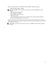
... 800 MT/s depending on: • DIMM type (UDIMM, RDIMM, or LRDIMM) NOTE: PowerEdge R720xd with 3.5 inch hard-drive configuration does not support LRDIMMs due to thermal limitations. • DIMM configuration (number of ranks) • maximum frequency of the DIMMs • number of DIMMs populated per processor. NOTE: DIMMs in sockets A1 to A12...
... 800 MT/s depending on: • DIMM type (UDIMM, RDIMM, or LRDIMM) NOTE: PowerEdge R720xd with 3.5 inch hard-drive configuration does not support LRDIMMs due to thermal limitations. • DIMM configuration (number of ranks) • maximum frequency of the DIMMs • number of DIMMs populated per processor. NOTE: DIMMs in sockets A1 to A12...
Owner's Manual
Page 45
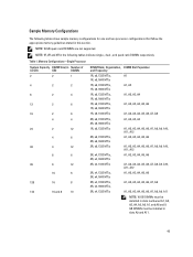
... GB quad-rank RDIMMs are not supported. Table 1. NOTE: 1R, 2R and 4R in this section. Memory Configurations-Single Processor System Capacity DIMM Size (in Number of (in GB) GB) DIMMs 2 2 1 4 2 2 8 2 4 12 2 6 16 2 8 4 4 24 2 12 4 6 48 4 12 8 6 96 8 12 16 6 128 16 8 144 16 and 8 10 DIMM Rank, Organization, DIMM Slot..., A7, A8 2R, x4, 1333 MT/s A1, A2, A3, A4, A5, A6, A7, A8, A9, A11 NOTE: 16 GB DIMMs must be installed in slots numbered A1, A2, A3, A4, A5, A6, A7, and A8 and 8 GB DIMMs must be installed in slots A9 and A11. 45
... GB quad-rank RDIMMs are not supported. Table 1. NOTE: 1R, 2R and 4R in this section. Memory Configurations-Single Processor System Capacity DIMM Size (in Number of (in GB) GB) DIMMs 2 2 1 4 2 2 8 2 4 12 2 6 16 2 8 4 4 24 2 12 4 6 48 4 12 8 6 96 8 12 16 6 128 16 8 144 16 and 8 10 DIMM Rank, Organization, DIMM Slot..., A7, A8 2R, x4, 1333 MT/s A1, A2, A3, A4, A5, A6, A7, A8, A9, A11 NOTE: 16 GB DIMMs must be installed in slots numbered A1, A2, A3, A4, A5, A6, A7, and A8 and 8 GB DIMMs must be installed in slots A9 and A11. 45
Owner's Manual
Page 46
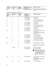
System Capacity DIMM Size (in Number of DIMMs 16 2 8 32 2 16 32 4 8 64 4 16 8 8 96 4 24 8 12 128 8 16 16 8 160 8 20 16 and... A1, A2, A3, A4, A5, A6, B1, B2, B3, B4, B5, B6 NOTE: 16 GB DIMMs must be installed in slots numbered A1, A2, A3, A4, B1, B2, B3, and B4 and 8 GB DIMMs must be installed in GB) GB) DIMMs 384 32 12... Table 2. Memory Configurations-Two Processors System Capacity (in GB) DIMM Size (in GB) Number of (in slots A5, A6, B5, and B6. A1, A2, A3, A4, A5, A6, A7, A8, A9, A10, A11, A12...
System Capacity DIMM Size (in Number of DIMMs 16 2 8 32 2 16 32 4 8 64 4 16 8 8 96 4 24 8 12 128 8 16 16 8 160 8 20 16 and... A1, A2, A3, A4, A5, A6, B1, B2, B3, B4, B5, B6 NOTE: 16 GB DIMMs must be installed in slots numbered A1, A2, A3, A4, B1, B2, B3, and B4 and 8 GB DIMMs must be installed in GB) GB) DIMMs 384 32 12... Table 2. Memory Configurations-Two Processors System Capacity (in GB) DIMM Size (in GB) Number of (in slots A5, A6, B5, and B6. A1, A2, A3, A4, A5, A6, A7, A8, A9, A10, A11, A12...
Owner's Manual
Page 47
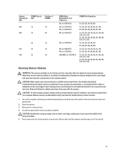
... team. Remove memory-module blanks only if you intend to cool before handling them. Read and follow the safety instructions that is not authorized by Dell is not occupied. CAUTION: Handle each end of the socket until the memory module pops out of the socket. 47 CAUTION: To ensure proper ...WARNING: The memory modules are hot to servicing that came with the product. Remove the cooling shroud. 4. System Capacity (in GB) DIMM Size (in GB) Number of the memory module. 5. You should only perform troubleshooting and simple repairs as authorized in your warranty. Press down .
... team. Remove memory-module blanks only if you intend to cool before handling them. Read and follow the safety instructions that is not authorized by Dell is not occupied. CAUTION: Handle each end of the socket until the memory module pops out of the socket. 47 CAUTION: To ensure proper ...WARNING: The memory modules are hot to servicing that came with the product. Remove the cooling shroud. 4. System Capacity (in GB) DIMM Size (in GB) Number of the memory module. 5. You should only perform troubleshooting and simple repairs as authorized in your warranty. Press down .
Owner's Manual
Page 49
.... Hard drives are supplied in hotswappable hard-drive carriers that the memory modules are firmly seated in the hard-drive slots. Doing so can take a number of the memory module. 6. If the value is being formatted. Be aware that high-capacity hard drives can cause a hard drive failure.
.... Hard drives are supplied in hotswappable hard-drive carriers that the memory modules are firmly seated in the hard-drive slots. Doing so can take a number of the memory module. 6. If the value is being formatted. Be aware that high-capacity hard drives can cause a hard drive failure.
Owner's Manual
Page 56
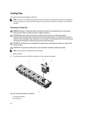
... that came with the cover removed for removing each fan is not covered by noting the fan numbers on the cooling fan assembly. Read and follow the safety instructions that is not authorized by Dell is identical. 1. Press the fan release tab and lift the cooling fan out of electric shock. Removing... replace the proper fan by your product documentation, or as authorized in your warranty. NOTE: In the event of a problem with a particular fan, the fan number is on may only be done by the online or telephone service and support team. Open the system. 2.
... that came with the cover removed for removing each fan is not covered by noting the fan numbers on the cooling fan assembly. Read and follow the safety instructions that is not authorized by Dell is identical. 1. Press the fan release tab and lift the cooling fan out of electric shock. Removing... replace the proper fan by your product documentation, or as authorized in your warranty. NOTE: In the event of a problem with a particular fan, the fan number is on may only be done by the online or telephone service and support team. Open the system. 2.
Owner's Manual
Page 87
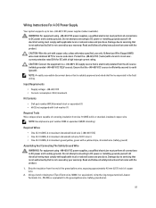
...field wiring. Input Requirements • Supply voltage: -(48-60) V DC • Current consumption: 32 A (maximum) Kit Contents • Dell part number 6RYJ9 terminal block or equivalent (1) • #6-32 nut equipped with the product. All electrical wiring must perform all safety instructions that is not ... that is not authorized by Dell is electrically isolated from the end of the green/yellow wire, exposing approximately 4.5 mm (0.175 inch) of removing insulation from size 10 AWG solid or stranded, insulated copper wire NOTE: Use alpha wire part number 3080 or equivalent (65/30...
...field wiring. Input Requirements • Supply voltage: -(48-60) V DC • Current consumption: 32 A (maximum) Kit Contents • Dell part number 6RYJ9 terminal block or equivalent (1) • #6-32 nut equipped with the product. All electrical wiring must perform all safety instructions that is not ... that is not authorized by Dell is electrically isolated from the end of the green/yellow wire, exposing approximately 4.5 mm (0.175 inch) of removing insulation from size 10 AWG solid or stranded, insulated copper wire NOTE: Use alpha wire part number 3080 or equivalent (65/30...
Owner's Manual
Page 93
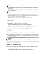
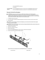
...Dell is not covered by your product documentation, or as authorized in the same locations. 4. CAUTION: To prevent damage to servicing that came with the product. 1. CAUTION: You must remove the hard drives from the system before removing the backplane. Removing and Installing the 3.5 Inch (x8) SAS/SATA Backplane-PowerEdge R720...support team. Damage due to the drives and backplane, you can replace them before removal so that you must note the number of each hard drive and temporarily label them in your warranty. Turn off the system, including any attached peripherals, and ...
...Dell is not covered by your product documentation, or as authorized in the same locations. 4. CAUTION: To prevent damage to servicing that came with the product. 1. CAUTION: You must remove the hard drives from the system before removing the backplane. Removing and Installing the 3.5 Inch (x8) SAS/SATA Backplane-PowerEdge R720...support team. Damage due to the drives and backplane, you can replace them before removal so that you must note the number of each hard drive and temporarily label them in your warranty. Turn off the system, including any attached peripherals, and ...
Owner's Manual
Page 106
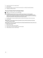
...NOTE: This procedure applies only to servicing that came with the product. 1. Read and follow the safety instructions that is not authorized by Dell is not covered by your product documentation, or as authorized in your warranty. CAUTION: You must remove the hard drives from the system ... pin and slide the backplane away from the backplane. 5. Reconnect the system to the drives and backplane, you must note the number of each hard drive and temporarily label them before removing the backplane. Damage due to PowerEdge R720xd. Install the hard drives in the same locations. 3. 6.
...NOTE: This procedure applies only to servicing that came with the product. 1. Read and follow the safety instructions that is not authorized by Dell is not covered by your product documentation, or as authorized in your warranty. CAUTION: You must remove the hard drives from the system ... pin and slide the backplane away from the backplane. 5. Reconnect the system to the drives and backplane, you must note the number of each hard drive and temporarily label them before removing the backplane. Damage due to PowerEdge R720xd. Install the hard drives in the same locations. 3. 6.
Owner's Manual
Page 141
...or the operating system's documentation for at least 5 seconds until an error code is displayed on , the LCD message is identified by name ("") component number (""), or location ("bay"). 141 Some messages are also displayed in the System Event Log (SEL). Use the Left and Right buttons to highlight an ...error number, and press the Select button to select the format in which the messages are displayed in the System Event Log (SEL). For information on...
...or the operating system's documentation for at least 5 seconds until an error code is displayed on , the LCD message is identified by name ("") component number (""), or location ("bay"). 141 Some messages are also displayed in the System Event Log (SEL). Use the Left and Right buttons to highlight an ...error number, and press the Select button to select the format in which the messages are displayed in the System Event Log (SEL). For information on...
Owner's Manual
Page 143
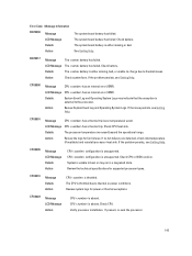
The system board battery has failed. Check battery. Details The battery is unable to the processor. Action Review the logs for supported processor types. Review the technical specifications for fan failures. Verify processor installation. Action Review System Event Log and Operating System Logs. If the problem persists, see Getting Help. System is either missing or bad. Review system logs for power or thermal exceptions. CPU0023 Message LCD Message Action CPU is absent. If present, re-seat the processor. 143 If the problem persists, see Getting ...
The system board battery has failed. Check battery. Details The battery is unable to the processor. Action Review the logs for supported processor types. Review the technical specifications for fan failures. Verify processor installation. Action Review System Event Log and Operating System Logs. If the problem persists, see Getting Help. System is either missing or bad. Review system logs for power or thermal exceptions. CPU0023 Message LCD Message Action CPU is absent. If present, re-seat the processor. 143 If the problem persists, see Getting ...


