
Getting Started Guide
Page 5
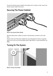
Turning on the System 5 Connect the system's power cable(s) to the system and, if a monitor is used, connect the monitor's power cable to the cable strap. Securing the Power Cable(s) Bend the system power cable(s), as an uninterruptible power supply (UPS) or a power distribution unit (PDU). Plug the other end of the power cable(s) into a grounded electrical outlet or a separate power source such as shown in the illustration, and attach to the monitor. Turning On The System Figure 5. Securing The Power Cable(s) Figure 4.
Turning on the System 5 Connect the system's power cable(s) to the system and, if a monitor is used, connect the monitor's power cable to the cable strap. Securing the Power Cable(s) Bend the system power cable(s), as an uninterruptible power supply (UPS) or a power distribution unit (PDU). Plug the other end of the power cable(s) into a grounded electrical outlet or a separate power source such as shown in the illustration, and attach to the monitor. Turning On The System Figure 5. Securing The Power Cable(s) Figure 4.

Getting Started Guide
Page 7
... management software, system updates, and system components that you do not understand a procedure in compliance with 1100 W DC power supply unit) 7 de México, S.A. NOM Information The following information is available online at support.dell.com/manuals. • The rack documentation included with your rack solution describes how to install your system into...
... management software, system updates, and system components that you do not understand a procedure in compliance with 1100 W DC power supply unit) 7 de México, S.A. NOM Information The following information is available online at support.dell.com/manuals. • The rack documentation included with your rack solution describes how to install your system into...
Getting Started Guide
Page 8
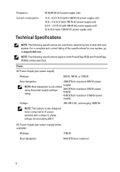
... calculated using the power supply wattage rating. Power AC Power Supply (per power supply) (when available) Wattage 1100 W Heat dissipation 4416 BTU/hour maximum 8 Frequency: Current consumption: 50 Hz/60 Hz (AC power supply unit) 12 A - 6.5 A (X 2) (with 1100 W AC power supply unit) 10 A - 5 A (X 2) (with 750 W AC power supply unit) 6.5 A - 3 A (X 2) (with 495 W AC power supply unit) 32 A (X 2) (with your system, go to both PowerEdge R720 and PowerEdge R720xd unless...
... calculated using the power supply wattage rating. Power AC Power Supply (per power supply) (when available) Wattage 1100 W Heat dissipation 4416 BTU/hour maximum 8 Frequency: Current consumption: 50 Hz/60 Hz (AC power supply unit) 12 A - 6.5 A (X 2) (with 1100 W AC power supply unit) 10 A - 5 A (X 2) (with 750 W AC power supply unit) 6.5 A - 3 A (X 2) (with 495 W AC power supply unit) 32 A (X 2) (with your system, go to both PowerEdge R720 and PowerEdge R720xd unless...
Getting Started Guide
Page 9
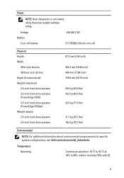
... dissipation is calculated using the power supply wattage rating. Voltage Battery Coin-cell battery -(48-60) V DC 3 V CR2032 Lithium coin cell Physical Height Width With rack latches Without rack latches Depth (includes bezel) Weight (maximum) 2.5-inch hard-drive systems 3.5-inch hard-drive systems (PowerEdge R720) 3.5-inch hard-drive systems (PowerEdge R720xd) Weight (empty) ... kg (71.5 lbs) 11.7 kg (25.7 lbs) 10.3 kg (22.7 lbs) Environmental NOTE: For additional information about environmental measurements for specific system configurations, see dell.com/environmental_datasheets.
... dissipation is calculated using the power supply wattage rating. Voltage Battery Coin-cell battery -(48-60) V DC 3 V CR2032 Lithium coin cell Physical Height Width With rack latches Without rack latches Depth (includes bezel) Weight (maximum) 2.5-inch hard-drive systems 3.5-inch hard-drive systems (PowerEdge R720) 3.5-inch hard-drive systems (PowerEdge R720xd) Weight (empty) ... kg (71.5 lbs) 11.7 kg (25.7 lbs) 10.3 kg (22.7 lbs) Environmental NOTE: For additional information about environmental measurements for specific system configurations, see dell.com/environmental_datasheets.

Owner's Manual
Page 5
... 78 Network Daughter Card...78 Removing The Network Daughter Card...78 Installing The Network Daughter Card...79 Processors...79 Removing A Processor...80 Installing A Processor...83 Power Supplies...84 Hot Spare Feature...85
... 78 Network Daughter Card...78 Removing The Network Daughter Card...78 Installing The Network Daughter Card...79 Processors...79 Removing A Processor...80 Installing A Processor...83 Power Supplies...84 Hot Spare Feature...85
Owner's Manual
Page 6
... The Power Supply Blank...91 System Battery...91 Replacing The System Battery...91 Hard-Drive Backplane...92 Removing The Hard-Drive Backplane...93 Installing The Hard-Drive Backplane...105 Removing The Optional Hard-Drive Backplane (Back 106 Installing The Optional Hard-Drive Backplane (Back 108 Control Panel...109 Removing The Control Panel (PowerEdge R720...
... The Power Supply Blank...91 System Battery...91 Replacing The System Battery...91 Hard-Drive Backplane...92 Removing The Hard-Drive Backplane...93 Installing The Hard-Drive Backplane...105 Removing The Optional Hard-Drive Backplane (Back 106 Installing The Optional Hard-Drive Backplane (Back 108 Control Panel...109 Removing The Control Panel (PowerEdge R720...
Owner's Manual
Page 9
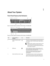
...power button controls the power supply output to locate a particular system within a rack. 1 About Your System Front-Panel Features And Indicators Figure 1. Front-Panel Features and Indicators (2.5 Inch Chassis)-PowerEdge R720 Item Indicator, Button, or Icon Description Connector 1 Power-on indicator, power button The power-on indicator lights when the system power... documentation. When one of a paper clip. Front-Panel Features and Indicators (3.5 Inch Chassis)-PowerEdge R720 Figure 2. Use this button only if directed to troubleshoot software and device driver errors when ...
...power button controls the power supply output to locate a particular system within a rack. 1 About Your System Front-Panel Features And Indicators Figure 1. Front-Panel Features and Indicators (2.5 Inch Chassis)-PowerEdge R720 Item Indicator, Button, or Icon Description Connector 1 Power-on indicator, power button The power-on indicator lights when the system power... documentation. When one of a paper clip. Front-Panel Features and Indicators (3.5 Inch Chassis)-PowerEdge R720 Figure 2. Use this button only if directed to troubleshoot software and device driver errors when ...
Owner's Manual
Page 11
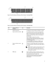
... ID button for more than 15 seconds. 3 Power-on indicator, power button The power-on indicator lights when the system power is pressed again. The power button controls the power supply output to do so by qualified support personnel or... by the operating system's documentation. 11 Figure 3. When one of a paper clip. NOTE: On ACPI-compliant operating systems, turning off the system using the end of these buttons is turned off . Front-Panel Features and Indicators (3.5 Inch Chassis)-PowerEdge...
... ID button for more than 15 seconds. 3 Power-on indicator, power button The power-on indicator lights when the system power is pressed again. The power button controls the power supply output to do so by qualified support personnel or... by the operating system's documentation. 11 Figure 3. When one of a paper clip. NOTE: On ACPI-compliant operating systems, turning off the system using the end of these buttons is turned off . Front-Panel Features and Indicators (3.5 Inch Chassis)-PowerEdge...

Owner's Manual
Page 14
... the hard drive that has an error. See Getting Help. If the hard drives are configured in Celsius or Fahrenheit. Power Displays the power output of the system in the Set home submenu of the Host, Model, or User String for the system Number Displays...ePSA). The following section describes system conditions and possible corrective actions associated with the power supply, check the 14 The display format can be configured in BTU/hr or Watts. The diagnostic indicators on PowerEdge R720xd. Option Description MAC Displays the MAC addresses for iDRAC, iSCSI, or Network...
... the hard drive that has an error. See Getting Help. If the hard drives are configured in Celsius or Fahrenheit. Power Displays the power output of the system in the Set home submenu of the Host, Model, or User String for the system Number Displays...ePSA). The following section describes system conditions and possible corrective actions associated with the power supply, check the 14 The display format can be configured in BTU/hr or Watts. The diagnostic indicators on PowerEdge R720xd. Option Description MAC Displays the MAC addresses for iDRAC, iSCSI, or Network...

Owner's Manual
Page 15
Corrective Action LED on the power supply. Re-seat the power supply by removing and reinstalling it. module blank, or back-filler bracket is removed. * Ambient temperature is too high. * External airflow is removed or has failed... Getting Help. Memory indicator Condition The indicator blinks amber if a memory error occurs. Update any required drivers for the location of range, or a failed power supply or voltage regulator). Temperature indicator Condition The indicator blinks amber if the system experiences a thermal error (for example, a temperature out of the following conditions ...
Corrective Action LED on the power supply. Re-seat the power supply by removing and reinstalling it. module blank, or back-filler bracket is removed. * Ambient temperature is too high. * External airflow is removed or has failed... Getting Help. Memory indicator Condition The indicator blinks amber if a memory error occurs. Update any required drivers for the location of range, or a failed power supply or voltage regulator). Temperature indicator Condition The indicator blinks amber if the system experiences a thermal error (for example, a temperature out of the following conditions ...
Owner's Manual
Page 18
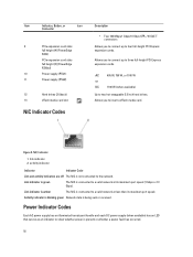
... port speed (1 Gbps or 10 Gbps). Power Indicator Codes Each AC power supply has an illuminated translucent handle and each DC power supply (when available) has an LED that serves as an indicator to show whether power is not connected to the network. Figure ... received. Item Indicator, Button, or Icon Connector 9 PCIe expansion card slots full height (4) (PowerEdge R720) PCIe expansion card slots full height (3) (PowerEdge R720xd) 10 Power supply (PSU1) 11 Power supply (PSU2) 12 Hard drives (2) (back) 13 vFlash media card slot NIC Indicator Codes Description ...
... port speed (1 Gbps or 10 Gbps). Power Indicator Codes Each AC power supply has an illuminated translucent handle and each DC power supply (when available) has an LED that serves as an indicator to show whether power is not connected to the network. Figure ... received. Item Indicator, Button, or Icon Connector 9 PCIe expansion card slots full height (4) (PowerEdge R720) PCIe expansion card slots full height (3) (PowerEdge R720xd) 10 Power supply (PSU1) 11 Power supply (PSU2) 12 Hard drives (2) (back) 13 vFlash media card slot NIC Indicator Codes Description ...

Owner's Manual
Page 19
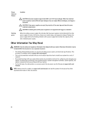
... green indicating that a valid power source is connected to the power supply and that the power supply is not connected. Indicates a problem with the flashing indicator. Swapping the opposite power supply to a Low Output configuration or vice versa, you must power down the system. 19 AC Power Supply Status Indicator 1. AC power supply status indicator/handle Figure 11. DC Power Supply Status Indicator 1. To...
... green indicating that a valid power source is connected to the power supply and that the power supply is not connected. Indicates a problem with the flashing indicator. Swapping the opposite power supply to a Low Output configuration or vice versa, you must power down the system. 19 AC Power Supply Status Indicator 1. AC power supply status indicator/handle Figure 11. DC Power Supply Status Indicator 1. To...
Owner's Manual
Page 20
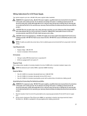
... both 220 V and 110 V input voltages. This document is available online at support.dell.com/ manuals. CAUTION: Combining AC and DC power supplies is mismatched with a power supply that provides documentation and tools for updates on support.dell.com/manuals and read the updates first because they often supersede information in this document, see the Glossary...
... both 220 V and 110 V input voltages. This document is available online at support.dell.com/ manuals. CAUTION: Combining AC and DC power supplies is mismatched with a power supply that provides documentation and tools for updates on support.dell.com/manuals and read the updates first because they often supersede information in this document, see the Glossary...

Owner's Manual
Page 35
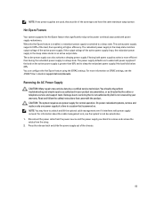
Figure 12. Lift the release latch next to ground Following tools are required for assembling cables for a DC power supply unit (PSU), when available: • AMP 90871-1 hand-crimping tool or equivalent • Wire-stripper pliers capable of removing insulation from the front panel. 4. 3 Installing ...
Figure 12. Lift the release latch next to ground Following tools are required for assembling cables for a DC power supply unit (PSU), when available: • AMP 90871-1 hand-crimping tool or equivalent • Wire-stripper pliers capable of removing insulation from the front panel. 4. 3 Installing ...
Owner's Manual
Page 84
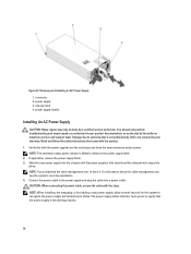
...ZIF socket. Place the heat sink on the system. 19. Press to the system only by the single power supply. 84 Rotate the socket-release lever near the unlock icon until it is redundant (1 + 1). Reconnect your...Power Supplies Your system supports either: • Two 495 W, 750 W, or 1100 W AC power supply modules or • Two 1100 W DC power supply modules (when available) When two identical power supplies are hot to removing a heat-sink or processor. 6. When only one power supply is installed, the power supply configuration is supplied to the system equally from both power supplies...
...ZIF socket. Place the heat sink on the system. 19. Press to the system only by the single power supply. 84 Rotate the socket-release lever near the unlock icon until it is redundant (1 + 1). Reconnect your...Power Supplies Your system supports either: • Two 495 W, 750 W, or 1100 W AC power supply modules or • Two 1100 W DC power supply modules (when available) When two identical power supplies are hot to removing a heat-sink or processor. 6. When only one power supply is installed, the power supply configuration is supplied to the system equally from both power supplies...
Owner's Manual
Page 85
... by a certified service technician. NOTE: You may only be of the load, thus operating at support.dell.com/manuals. If the output voltage of the active power supply drops, the redundant power supply in the sleep state returns to a sleep state. You should only perform troubleshooting and simple repairs as ...efficiency. Hot Spare Feature Your system supports the Hot Spare feature that is not authorized by Dell is not covered by the online or telephone service and support team. The active power supply supports 100% of the same type and have to unlatch and lift the optional cable ...
... by a certified service technician. NOTE: You may only be of the load, thus operating at support.dell.com/manuals. If the output voltage of the active power supply drops, the redundant power supply in the sleep state returns to a sleep state. You should only perform troubleshooting and simple repairs as ...efficiency. Hot Spare Feature Your system supports the Hot Spare feature that is not authorized by Dell is not covered by the online or telephone service and support team. The active power supply supports 100% of the same type and have to unlatch and lift the optional cable ...
Owner's Manual
Page 86
..., hot-swapping, or hot-adding a new power supply, allow several seconds for the system to signify that is not authorized by Dell is functioning properly. 86 The power-supply status indicator turns green to recognize the power supply and determine its status. Removing and Installing an AC Power Supply 1. CAUTION: When connecting the power cable, secure the cable with the...
..., hot-swapping, or hot-adding a new power supply, allow several seconds for the system to signify that is not authorized by Dell is functioning properly. 86 The power-supply status indicator turns green to recognize the power supply and determine its status. Removing and Installing an AC Power Supply 1. CAUTION: When connecting the power cable, secure the cable with the...
Owner's Manual
Page 87
...the -(48-60) V DC source is not covered by Dell is efficiently secured to earth (ground). WARNING: For equipment using -(48-60) V DC power supplies, a qualified electrician must perform all connections to DC power and to safety grounds. Strip the insulation from the end ...wire (safety ground) Assembling And Connecting The Safety Ground Wire WARNING: For equipment using -(48-60) V DC power supplies, a qualified electrician must perform all connections to DC power and to safety grounds. Do not attempt connecting to the green/yellow wire (safety ground wire). 87 Damage ...
...the -(48-60) V DC source is not covered by Dell is efficiently secured to earth (ground). WARNING: For equipment using -(48-60) V DC power supplies, a qualified electrician must perform all connections to DC power and to safety grounds. Strip the insulation from the end ...wire (safety ground) Assembling And Connecting The Safety Ground Wire WARNING: For equipment using -(48-60) V DC power supplies, a qualified electrician must perform all connections to DC power and to safety grounds. Do not attempt connecting to the green/yellow wire (safety ground wire). 87 Damage ...

Owner's Manual
Page 88
... captive screws must perform all safety instructions that is not authorized by Dell is not covered by your warranty. WARNING: Reversing polarity when connecting DC power wires can permanently damage the power supply or the system. 2. Insert the copper ends into the power supply. 88 Figure 48. grounding post 3. Do not attempt connecting to servicing that...
... captive screws must perform all safety instructions that is not authorized by Dell is not covered by your warranty. WARNING: Reversing polarity when connecting DC power wires can permanently damage the power supply or the system. 2. Insert the copper ends into the power supply. 88 Figure 48. grounding post 3. Do not attempt connecting to servicing that...

Owner's Manual
Page 89
... to DC power and to servicing that is not authorized by Dell is powered on. Press the release latch and slide the power supply out of the chassis. 89 DC power socket 2. grounding wire Removing A DC Power Supply WARNING: For equipment using -(48-60) V DC power supplies, a qualified... your warranty. Figure 49. Assembling the DC Input Power Wires 1. CAUTION: The system requires one power supply at a time in a system that came with power supply removal. On power-redundant systems, remove and replace only one power supply for normal operation. Disconnect the safety ground wire....
... to DC power and to servicing that is not authorized by Dell is powered on. Press the release latch and slide the power supply out of the chassis. 89 DC power socket 2. grounding wire Removing A DC Power Supply WARNING: For equipment using -(48-60) V DC power supplies, a qualified... your warranty. Figure 49. Assembling the DC Input Power Wires 1. CAUTION: The system requires one power supply at a time in a system that came with power supply removal. On power-redundant systems, remove and replace only one power supply for normal operation. Disconnect the safety ground wire....


