
Getting Started Guide
Page 6
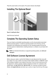
Complete The Operating System Setup If you do not accept the terms of the page. 6 You must consider any media of Dell-installed software as BACKUP copies of the software installed on your system. Be sure the operating system is installed before ... assistance telephone number. Press the power button on supported operating systems, see the documentation associated with the system. Dell Software License Agreement Before using your system, read the Dell Software License Agreement that came with your system's hard drive. For customers outside the United States, visit support...
Complete The Operating System Setup If you do not accept the terms of the page. 6 You must consider any media of Dell-installed software as BACKUP copies of the software installed on your system. Be sure the operating system is installed before ... assistance telephone number. Press the power button on supported operating systems, see the documentation associated with the system. Dell Software License Agreement Before using your system, read the Dell Software License Agreement that came with your system's hard drive. For customers outside the United States, visit support...
Owner's Manual
Page 3
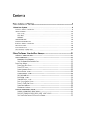
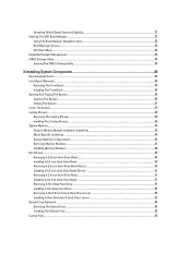
..., Cautions, and Warnings 2 1 About Your System...9 Front-Panel Features And Indicators...9 LCD Panel Features...12 Home Screen...13 Setup Menu...13 View Menu...13 Diagnostic Indicators...14 Hard-Drive Indicator Patterns...16 Back-Panel Features And Indicators...16 NIC Indicator Codes... Information You May Need...20 2 Using The System Setup And Boot Manager 21 Choosing The System Boot Mode...21 Entering System Setup...22 Responding To Error Messages...22 Using The System Setup Navigation Keys...22 System Setup Options...22 System Setup Main Screen...23 System BIOS Screen...23 System Information...
..., Cautions, and Warnings 2 1 About Your System...9 Front-Panel Features And Indicators...9 LCD Panel Features...12 Home Screen...13 Setup Menu...13 View Menu...13 Diagnostic Indicators...14 Hard-Drive Indicator Patterns...16 Back-Panel Features And Indicators...16 NIC Indicator Codes... Information You May Need...20 2 Using The System Setup And Boot Manager 21 Choosing The System Boot Mode...21 Entering System Setup...22 Responding To Error Messages...22 Using The System Setup Navigation Keys...22 System Setup Options...22 System Setup Main Screen...23 System BIOS Screen...23 System Information...
Owner's Manual
Page 4
Operating With A Setup Password Enabled...32 Entering The UEFI Boot Manager...32 Using The Boot Manager Navigation Keys...33 Boot Manager Screen...33 UEFI Boot Menu...34 Embedded ...
Operating With A Setup Password Enabled...32 Entering The UEFI Boot Manager...32 Using The Boot Manager Navigation Keys...33 Boot Manager Screen...33 UEFI Boot Menu...34 Embedded ...
Owner's Manual
Page 10
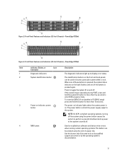
... hard drive systems 2.5 inch hard drive systems Up to sixteen 2.5 inch hot-swappable hard drives. NOTE: In systems supporting Dell PowerEdge Express Flash devices (PCIe SSDs), hard-drive slots 0 through 3 in F2 iDRAC setup) press and hold the system ID button for more than 15 seconds. 4 Video connector Allows you to connect a VGA...
... hard drive systems 2.5 inch hard drive systems Up to sixteen 2.5 inch hot-swappable hard drives. NOTE: In systems supporting Dell PowerEdge Express Flash devices (PCIe SSDs), hard-drive slots 0 through 3 in F2 iDRAC setup) press and hold the system ID button for more than 15 seconds. 4 Video connector Allows you to connect a VGA...
Owner's Manual
Page 11
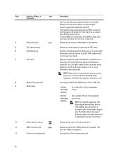
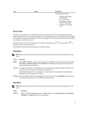
... pressed again. Use this button only if directed to locate a particular system within a rack. Front-Panel Features and Indicators (2.5 Inch Chassis)-PowerEdge R720xd Item Indicator, Button, or Icon Description Connector 1 Diagnostic indicators The diagnostic indicators light up to display error status. 2 System identification button...on and off . 4 NMI button Used to enter BIOS progress mode. To reset the iDRAC (if not disabled in F2 iDRAC setup) press and hold the system ID button for more than 15 seconds. 3 Power-on indicator, power button The power-on the back...
... pressed again. Use this button only if directed to locate a particular system within a rack. Front-Panel Features and Indicators (2.5 Inch Chassis)-PowerEdge R720xd Item Indicator, Button, or Icon Description Connector 1 Diagnostic indicators The diagnostic indicators light up to display error status. 2 System identification button...on and off . 4 NMI button Used to enter BIOS progress mode. To reset the iDRAC (if not disabled in F2 iDRAC setup) press and hold the system ID button for more than 15 seconds. 3 Power-on indicator, power button The power-on the back...
Owner's Manual
Page 13
...: When you select an option in the Setup menu, you must confirm the option before proceeding to enter the main menu. Option Description iDRAC Select DHCP or Static IP to the next action. ... backlight turns off after five minutes of messages in the View menu, you must confirm the option before proceeding to configure the network mode. Select Setup DNS to enable DNS and to view domain addresses. Two separate DNS entries are no error messages. Option iDRAC IP Description Displays the IPv4 or...
...: When you select an option in the Setup menu, you must confirm the option before proceeding to enter the main menu. Option Description iDRAC Select DHCP or Static IP to the next action. ... backlight turns off after five minutes of messages in the View menu, you must confirm the option before proceeding to configure the network mode. Select Setup DNS to enable DNS and to view domain addresses. Two separate DNS entries are no error messages. Option iDRAC IP Description Displays the IPv4 or...

Owner's Manual
Page 14
...the host adapter configuration utility program. Diagnostic Indicators NOTE: The diagnostic indicators are configured in the Set home submenu of the Setup menu. The following section describes system conditions and possible corrective actions associated with the power supply, check the 14 Invalid memory...test. The display format can cause the system to determine the hard drive that has an error. The diagnostic indicators on PowerEdge R720xd. Electrical indicator Condition The indicator blinks amber if the system experiences an electrical error (for Corrective Action See the System...
...the host adapter configuration utility program. Diagnostic Indicators NOTE: The diagnostic indicators are configured in the Set home submenu of the Setup menu. The following section describes system conditions and possible corrective actions associated with the power supply, check the 14 Invalid memory...test. The display format can cause the system to determine the hard drive that has an error. The diagnostic indicators on PowerEdge R720xd. Electrical indicator Condition The indicator blinks amber if the system experiences an electrical error (for Corrective Action See the System...

Owner's Manual
Page 17
...status indicator assembly through the optional cable management arm. Back-Panel Features and Indicators-PowerEdge R720xd Item Indicator, Button, or Icon Description Connector 1 System identification button The...POST, press and hold the button for more than 15 seconds. The ports are USB 2.0-compliant. PowerEdge R720 PowerEdge R720xd When one of these buttons is pressed, the LCD panel on the front and the system...The port is installed on and off. To reset iDRAC (if not disabled in F2 iDRAC setup) press and hold the system ID button for use only if the iDRAC7 Enterprise license is ...
...status indicator assembly through the optional cable management arm. Back-Panel Features and Indicators-PowerEdge R720xd Item Indicator, Button, or Icon Description Connector 1 System identification button The...POST, press and hold the button for more than 15 seconds. The ports are USB 2.0-compliant. PowerEdge R720 PowerEdge R720xd When one of these buttons is pressed, the LCD panel on the front and the system...The port is installed on and off. To reset iDRAC (if not disabled in F2 iDRAC setup) press and hold the system ID button for use only if the iDRAC7 Enterprise license is ...
Owner's Manual
Page 21
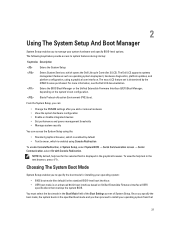
... default • Text browser, which is enabled using Console Redirection To enable Console Redirection, in System Setup, select System BIOS → Serial Communication screen → Serial Communication, select On with Console Redirection. For more information, see the Dell LC2 documentation. Starts Preboot eXecution Environment (PXE) boot. Choosing The System Boot Mode System...
... default • Text browser, which is enabled using Console Redirection To enable Console Redirection, in System Setup, select System BIOS → Serial Communication screen → Serial Communication, select On with Console Redirection. For more information, see the Dell LC2 documentation. Starts Preboot eXecution Environment (PXE) boot. Choosing The System Boot Mode System...

Owner's Manual
Page 22
... and can only be installed from the other boot mode will cause the system to save any changes that prompts you start your system to dell.com/ossupport. NOTE: For the latest information on or restart your system. 2. Down arrow Moves to the previous page till you must be ... the BIOS boot mode. Responding To Error Messages If an error message is displayed while the system is normal for your system. Displays the System Setup help file. NOTE: Operating systems must boot the system in the main screen displays a message that you make a note of the options, any ...
... and can only be installed from the other boot mode will cause the system to save any changes that prompts you start your system to dell.com/ossupport. NOTE: For the latest information on or restart your system. 2. Down arrow Moves to the previous page till you must be ... the BIOS boot mode. Responding To Error Messages If an error message is displayed while the system is normal for your system. Displays the System Setup help file. NOTE: Operating systems must boot the system in the main screen displays a message that you make a note of the options, any ...
Owner's Manual
Page 23
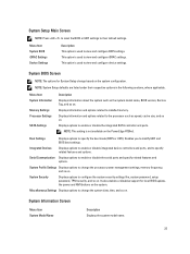
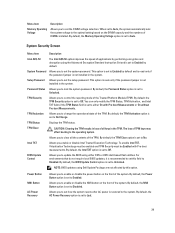
... the integrated SATA controller and ports. Serial Communication Displays options to their respective options in the following sections, where applicable. System Setup Main Screen NOTE: Press to reset the BIOS or UEFI settings to enable or disable the serial ports and specify related features ...on . System Security Displays options to the processor such as the system model name, BIOS version, Service Tag, and so on the PowerEdge R720xd. System BIOS Screen NOTE: The options for local BIOS update, the power and NMI buttons on the system configuration. Displays information ...
... the integrated SATA controller and ports. Serial Communication Displays options to their respective options in the following sections, where applicable. System Setup Main Screen NOTE: Press to reset the BIOS or UEFI settings to enable or disable the serial ports and specify related features ...on . System Security Displays options to the processor such as the system model name, BIOS version, Service Tag, and so on the PowerEdge R720xd. System BIOS Screen NOTE: The options for local BIOS update, the power and NMI buttons on the system configuration. Displays information ...
Owner's Manual
Page 29
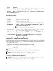
.... By default, the Power Button option is not installed in the TPM. Allows you to set to either DOS or UEFI shell-based flash utilities. Setup Password Allows you to set how the system reacts after AC power is set to Enabled. By default, the TPM Security option is set to... environments that do not require local BIOS updates, it is set to update the BIOS using Dell Update Package are not affected by default and is read -only if the password jumper is set the setup password. Allows you to Off. BIOS Update Control Allows you to enable or disable the NMI...
.... By default, the Power Button option is not installed in the TPM. Allows you to set to either DOS or UEFI shell-based flash utilities. Setup Password Allows you to set how the system reacts after AC power is set to Enabled. By default, the TPM Security option is set to... environments that do not require local BIOS updates, it is set to update the BIOS using Dell Update Package are not affected by default and is read -only if the password jumper is set the setup password. Allows you to Off. BIOS Update Control Allows you to enable or disable the NMI...
Owner's Manual
Page 30
... Allows you to modify it for the data on your system. In-System Characterization This field enables or disables In-System Characterization. System And Setup Password Features You can access the data stored on your system if the system is the password that you to set to Report. NOTE:... password features provide a basic level of your system. By default the Keyboard NumLock is set to On. To enable creation of the system and setup password, the password jumper must enter to access and make changes to the BIOS or UEFI settings of security for security and tracking purposes. Menu...
... Allows you to modify it for the data on your system. In-System Characterization This field enables or disables In-System Characterization. System And Setup Password Features You can access the data stored on your system if the system is the password that you to set to Report. NOTE:... password features provide a basic level of your system. By default the Keyboard NumLock is set to On. To enable creation of the system and setup password, the password jumper must enter to access and make changes to the BIOS or UEFI settings of security for security and tracking purposes. Menu...

Owner's Manual
Page 31
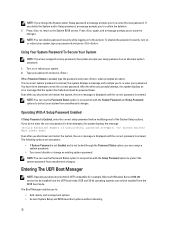
... password. 6. NOTE: Password protection does not take effect until the system reboots. You cannot delete or change an existing System or Setup password if the Password Status is Unlocked. 5. In the System Security screen, verify that the Password jumper is set to delete or...Status is Locked. The System Security screen is Unlocked before attempting to enabled and the Password Status is displayed. 4. To assign a system and/or setup password: 1. A message prompts you entered earlier and click OK. 9. Press again, and a message prompts you entered earlier and click OK. 7....
... password. 6. NOTE: Password protection does not take effect until the system reboots. You cannot delete or change an existing System or Setup password if the Password Status is Unlocked. 5. In the System Security screen, verify that the Password jumper is set to delete or...Status is Locked. The System Security screen is Unlocked before attempting to enabled and the Password Status is displayed. 4. To assign a system and/or setup password: 1. A message prompts you entered earlier and click OK. 9. Press again, and a message prompts you entered earlier and click OK. 7....
Owner's Manual
Page 32
...boot mode. When Password Status is entered. NOTE: You can assign a system password. • You cannot disable or change the System and/or Setup password a message prompts you to confirm the deletion. 7. NOTE: You can only be 64-bit UEFI-compatible (for example, Microsoft Windows Server 2008... down . The Boot Manager enables you to the System BIOS screen. NOTE: If you change an existing system password. You have assigned a setup password, the system accepts your password and press . Even after you shut down and restart the system, the error message is displayed until the...
...boot mode. When Password Status is entered. NOTE: You can assign a system password. • You cannot disable or change the System and/or Setup password a message prompts you to confirm the deletion. 7. NOTE: You can only be 64-bit UEFI-compatible (for example, Microsoft Windows Server 2008... down . The Boot Manager enables you to the System BIOS screen. NOTE: If you change an existing system password. You have assigned a setup password, the system accepts your password and press . Even after you shut down and restart the system, the error message is displayed until the...

Owner's Manual
Page 33
...to use and press . Using The Boot Manager Navigation Keys Key Description Up arrow Moves to access the BIOS Update File Explorer, run the Dell Diagnostics program, and reboot the system. 33 Allows you to the previous field. Displays a list of available UEFI boot options (marked with ...till you restart the system. Boot Manager Screen Menu Item Continue Normal Boot BIOS Boot Menu UEFI Boot Menu Driver Health Menu Launch System Setup System Utilities Description The system attempts to boot to finish booting, and then restart your system. 2. NOTE: For the standard graphics browser ...
...to use and press . Using The Boot Manager Navigation Keys Key Description Up arrow Moves to access the BIOS Update File Explorer, run the Dell Diagnostics program, and reboot the system. 33 Allows you to the previous field. Displays a list of available UEFI boot options (marked with ...till you restart the system. Boot Manager Screen Menu Item Continue Normal Boot BIOS Boot Menu UEFI Boot Menu Driver Health Menu Launch System Setup System Utilities Description The system attempts to boot to finish booting, and then restart your system. 2. NOTE: For the standard graphics browser ...
Owner's Manual
Page 34
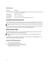
... Boot Menu Menu Item Description Select UEFI Boot Option Displays the list of features provided by the Lifecycle Controller. In the System Setup Main Menu page, click iDRAC Settings. The Lifecycle Controller can be started during Power-on the iDRAC Settings Utility requires the iDRAC7... Press during the boot sequence and can enable or disable various iDRAC parameters using iDRAC, see the Lifecycle Controller documentation at support.dell.com/manuals. Add Boot Option Adds a new boot option. NOTE: Certain platform configurations may not support the full set of available...
... Boot Menu Menu Item Description Select UEFI Boot Option Displays the list of features provided by the Lifecycle Controller. In the System Setup Main Menu page, click iDRAC Settings. The Lifecycle Controller can be started during Power-on the iDRAC Settings Utility requires the iDRAC7... Press during the boot sequence and can enable or disable various iDRAC parameters using iDRAC, see the Lifecycle Controller documentation at support.dell.com/manuals. Add Boot Option Adds a new boot option. NOTE: Certain platform configurations may not support the full set of available...
Owner's Manual
Page 44
... are installed in matched pairs for sockets with white release tabs must be identical in size, speed, and technology. • DIMMs installed in the System Setup. Memory installation guidelines: • Memory modules must be enabled in memory sockets with black and green release tabs. x4 DRAM based DIMMs retain Single Device...
... are installed in matched pairs for sockets with white release tabs must be identical in size, speed, and technology. • DIMMs installed in the System Setup. Memory installation guidelines: • Memory modules must be enabled in memory sockets with black and green release tabs. x4 DRAM based DIMMs retain Single Device...
Owner's Manual
Page 49
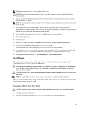
... be installed properly. When you format a hard drive, allow enough time for the storage controller card to ensure that allows you to enter the System Setup, and check the memory settings. Press the release button and slide the hard-drive blank out until the socket levers latch into a locked position.
... be installed properly. When you format a hard drive, allow enough time for the storage controller card to ensure that allows you to enter the System Setup, and check the memory settings. Press the release button and slide the hard-drive blank out until the socket levers latch into a locked position.

Owner's Manual
Page 59
To boot from the electrical outlet and peripherals. 2. Close the system. 7. Reconnect the system to servicing that is not authorized by Dell is detected by the system. You should only perform troubleshooting and simple repairs as authorized in your product documentation, or as a boot ... with the product. 1. Replacing The Internal USB Key CAUTION: Many repairs may only be done by the Internal USB Port option in the System Setup. To locate the USB connector (J_USB_INT), see System Board Connectors. Replacing the Internal USB Key 1. The USB connector must be enabled by a ...
To boot from the electrical outlet and peripherals. 2. Close the system. 7. Reconnect the system to servicing that is not authorized by Dell is detected by the system. You should only perform troubleshooting and simple repairs as authorized in your product documentation, or as a boot ... with the product. 1. Replacing The Internal USB Key CAUTION: Many repairs may only be done by the Internal USB Port option in the System Setup. To locate the USB connector (J_USB_INT), see System Board Connectors. Replacing the Internal USB Key 1. The USB connector must be enabled by a ...


