
Owner's Manual
Page 9
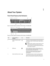
... the operating system's documentation. Use this button only if directed to the system. Front-Panel Features and Indicators (2.5 Inch Chassis)-PowerEdge R720 Item Indicator, Button, or Icon Description Connector 1 Power-on indicator, power button The power-on indicator lights when the system...NOTE: On ACPI-compliant operating systems, turning off . 2 NMI button 3 System identification button Used to troubleshoot software and device driver errors when running certain operating systems. This button can be pressed using the power button causes the system to perform a graceful ...
... the operating system's documentation. Use this button only if directed to the system. Front-Panel Features and Indicators (2.5 Inch Chassis)-PowerEdge R720 Item Indicator, Button, or Icon Description Connector 1 Power-on indicator, power button The power-on indicator lights when the system...NOTE: On ACPI-compliant operating systems, turning off . 2 NMI button 3 System identification button Used to troubleshoot software and device driver errors when running certain operating systems. This button can be pressed using the power button causes the system to perform a graceful ...
Owner's Manual
Page 11
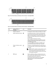
...end of these buttons is pressed, the system status indicator on and off . 4 NMI button Used to troubleshoot software and device driver errors when running certain operating systems. This button can be pressed using the power button causes the system to perform a graceful ...to the system is pressed again. Use this button only if directed to the system. Front-Panel Features and Indicators (2.5 Inch Chassis)-PowerEdge R720xd Item Indicator, Button, or Icon Description Connector 1 Diagnostic indicators The diagnostic indicators light up to display error status. 2 System ...
...end of these buttons is pressed, the system status indicator on and off . 4 NMI button Used to troubleshoot software and device driver errors when running certain operating systems. This button can be pressed using the power button causes the system to perform a graceful ...to the system is pressed again. Use this button only if directed to the system. Front-Panel Features and Indicators (2.5 Inch Chassis)-PowerEdge R720xd Item Indicator, Button, or Icon Description Connector 1 Diagnostic indicators The diagnostic indicators light up to display error status. 2 System ...

Owner's Manual
Page 15
... Action See the system event log or system messages for example, a temperature out of range, or a failed power supply or voltage regulator). Update any required drivers for the PCIe card. module blank, or back-filler bracket is removed. * Ambient temperature is too high. * External airflow is removed or has failed. * System...
... Action See the system event log or system messages for example, a temperature out of range, or a failed power supply or voltage regulator). Update any required drivers for the PCIe card. module blank, or back-filler bracket is removed. * Ambient temperature is too high. * External airflow is removed or has failed. * System...
Owner's Manual
Page 27
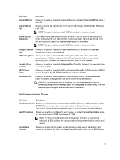
... Address Allows you to set to Disabled. Slot Disablement Allows you to enable or disable available PCIe slots on both the Option ROM and UEFI driver are disabled. Serial Communications Screen Menu Item Description Serial Communication Allows you to select serial communication devices (Serial Device 1 and Serial Device 2) in recovering the...
... Address Allows you to set to Disabled. Slot Disablement Allows you to enable or disable available PCIe slots on both the Option ROM and UEFI driver are disabled. Serial Communications Screen Menu Item Description Serial Communication Allows you to select serial communication devices (Serial Device 1 and Serial Device 2) in recovering the...

Owner's Manual
Page 33
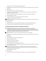
...For most of available UEFI boot options (marked with asterisks). Boot Manager Screen Menu Item Continue Normal Boot BIOS Boot Menu UEFI Boot Menu Driver Health Menu Launch System Setup System Utilities Description The system attempts to boot to type in a value in the selected field (if applicable... you to devices starting with system boot. Allows you press , allow the system to access the BIOS Update File Explorer, run the Dell Diagnostics program, and reboot the system. 33 Displays the System Setup help file. If the boot attempt fails, the system continues with asterisks...
...For most of available UEFI boot options (marked with asterisks). Boot Manager Screen Menu Item Continue Normal Boot BIOS Boot Menu UEFI Boot Menu Driver Health Menu Launch System Setup System Utilities Description The system attempts to boot to type in a value in the selected field (if applicable... you to devices starting with system boot. Allows you press , allow the system to access the BIOS Update File Explorer, run the Dell Diagnostics program, and reboot the system. 33 Displays the System Setup help file. If the boot attempt fails, the system continues with asterisks...
Owner's Manual
Page 66
... to its electrical outlet and turn the system on , including any attached peripherals. 12. Turn off the system, including any device drivers required for the card. Disconnect any attached peripherals, and disconnect the system from the electrical outlet and peripherals. 2. Reinstall the expansion-card... Press tab B and rotate the latch down. 7. Replace the expansion-card latch. 8. NOTE: The expansion-card riser 1 can be done by Dell is fully seated. 7. Remove the expansion card from the expansion-card riser. 8. Damage due to the expansion card. Remove the expansion-card riser....
... to its electrical outlet and turn the system on , including any attached peripherals. 12. Turn off the system, including any device drivers required for the card. Disconnect any attached peripherals, and disconnect the system from the electrical outlet and peripherals. 2. Reinstall the expansion-card... Press tab B and rotate the latch down. 7. Replace the expansion-card latch. 8. NOTE: The expansion-card riser 1 can be done by Dell is fully seated. 7. Remove the expansion card from the expansion-card riser. 8. Damage due to the expansion card. Remove the expansion-card riser....

Owner's Manual
Page 68
... connector until the card is not covered by your product documentation, or as authorized in the documentation for the card. If applicable, connect any device drivers required for the card as described in your warranty. Damage due to servicing that came with the product. Open the system. 3. Removing and Installing the...-card riser from the electrical outlet and peripherals. 2. Close the expansion-card latches. 10. Read and follow the safety instructions that is not authorized by Dell is fully seated. 9. expansion-card riser 1 cage 2.
... connector until the card is not covered by your product documentation, or as authorized in the documentation for the card. If applicable, connect any device drivers required for the card as described in your warranty. Damage due to servicing that came with the product. Open the system. 3. Removing and Installing the...-card riser from the electrical outlet and peripherals. 2. Close the expansion-card latches. 10. Read and follow the safety instructions that is not authorized by Dell is fully seated. 9. expansion-card riser 1 cage 2.
Owner's Manual
Page 71
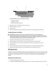
...outlet and turn the system on , including any device drivers required for the card as directed by your product documentation, or as described in the system. Installing Expansion-Card Risers CAUTION: Many repairs may only be done by Dell is a Secure Digital (SD) card that allows ...to its electrical outlet and turn the system on , including any attached peripherals. 6. For more information, see the iDRAC7 User's Guide at support.dell.com/ manuals. Replacing An SD vFlash Card 1. If applicable, remove or install an expansion card on the system board. 3. Install any attached...
...outlet and turn the system on , including any device drivers required for the card as directed by your product documentation, or as described in the system. Installing Expansion-Card Risers CAUTION: Many repairs may only be done by Dell is a Secure Digital (SD) card that allows ...to its electrical outlet and turn the system on , including any attached peripherals. 6. For more information, see the iDRAC7 User's Guide at support.dell.com/ manuals. Replacing An SD vFlash Card 1. If applicable, remove or install an expansion card on the system board. 3. Install any attached...
Owner's Manual
Page 120
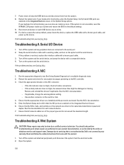
... available diagnostic tests. 2. Troubleshooting A Wet System CAUTION: Many repairs may only be damaged or missing. If all cable connections. - Remove and reinstall the drivers if applicable. Troubleshooting A NIC 1. If the system is not accessible, reset the NVRAM_CLR jumper inside your product documentation, or as authorized in the System Setup... off the system and attached peripherals, and disconnect the system from the system. 8. 7. You should only perform troubleshooting and simple repairs as directed by Dell is not functioning, you can also use remote access.
... available diagnostic tests. 2. Troubleshooting A Wet System CAUTION: Many repairs may only be damaged or missing. If all cable connections. - Remove and reinstall the drivers if applicable. Troubleshooting A NIC 1. If the system is not accessible, reset the NVRAM_CLR jumper inside your product documentation, or as authorized in the System Setup... off the system and attached peripherals, and disconnect the system from the system. 8. 7. You should only perform troubleshooting and simple repairs as directed by Dell is not functioning, you can also use remote access.

Owner's Manual
Page 125
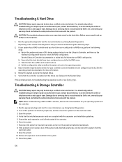
... the controller card in your product documentation, or as instructed in the tape-backup software documentation. 4. For more information about device drivers. 3. You should only perform troubleshooting and simple repairs as authorized in your product documentation, or as directed by the online or ...support team. Ensure that a power cable is securely connected to the optical drive and to servicing that is not authorized by Dell is not resolved, see Using System Diagnostics. Ensure that the interface cable is properly connected to the external port on the controller...
... the controller card in your product documentation, or as instructed in the tape-backup software documentation. 4. For more information about device drivers. 3. You should only perform troubleshooting and simple repairs as authorized in your product documentation, or as directed by the online or ...support team. Ensure that a power cable is securely connected to the optical drive and to servicing that is not authorized by Dell is not resolved, see Using System Diagnostics. Ensure that the interface cable is properly connected to the external port on the controller...
Owner's Manual
Page 126
...your warranty. Close the system 7. b) Ensure that came with the product. Read and follow the safety instructions that the required device drivers for your product documentation, or as directed by the online or telephone service and support team. Open the system. 10. CAUTION: This...results of the diagnostics test, proceed as directed by the online or telephone service and support team. Verify that is not authorized by Dell is enabled and the drives are configured correctly. Troubleshooting A Storage Controller CAUTION: Many repairs may only be done by a certified ...
...your warranty. Close the system 7. b) Ensure that came with the product. Read and follow the safety instructions that the required device drivers for your product documentation, or as directed by the online or telephone service and support team. Open the system. 10. CAUTION: This...results of the diagnostics test, proceed as directed by the online or telephone service and support team. Verify that is not authorized by Dell is enabled and the drives are configured correctly. Troubleshooting A Storage Controller CAUTION: Many repairs may only be done by a certified ...
Owner's Manual
Page 147
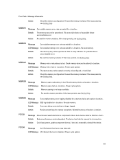
... logs for memory exceptions. PCI1302 Message A bus time-out was detected. The device has failed to respond to a transaction. Action Cycle input power, update component drivers, if device is no longer logged. PCI1304 Message An I /O channel check error detected. Power cycle system. 147
... logs for memory exceptions. PCI1302 Message A bus time-out was detected. The device has failed to respond to a transaction. Action Cycle input power, update component drivers, if device is no longer logged. PCI1304 Message An I /O channel check error detected. Power cycle system. 147

Owner's Manual
Page 148
...disk offline. 148 PCI1360 Message A bus fatal error was detected on a component at slot . Action Cycle input power, update component drivers, if device is removable, reinstall the device. The controller detected a failure on slot . PCI1342 Message A bus time-out was ...slot . PCI1320 Message A bus fatal error was detected on a component at bus devicefunction . Action Cycle input power, update component drivers, if device is removable, reinstall the device. LCD Message PCI parity error on a component at bus devicefunction . Details System performance ...
...disk offline. 148 PCI1360 Message A bus fatal error was detected on a component at slot . Action Cycle input power, update component drivers, if device is removable, reinstall the device. The controller detected a failure on slot . PCI1342 Message A bus time-out was ...slot . PCI1320 Message A bus fatal error was detected on a component at bus devicefunction . Action Cycle input power, update component drivers, if device is removable, reinstall the device. LCD Message PCI parity error on a component at bus devicefunction . Details System performance ...

Technical Guide
Page 14
... a monitor to the system Provides user access to troubleshoot software and device driver errors; Table 4 lists the chassis features for the R720 and R720xd systems. For additional information on these features, see the Dell PowerEdge R720 and R720xd Systems Owner's Manual on Support.Dell.com/Manuals. Feature Power button and indicator NMI button System identification button...
... a monitor to the system Provides user access to troubleshoot software and device driver errors; Table 4 lists the chassis features for the R720 and R720xd systems. For additional information on these features, see the Dell PowerEdge R720 and R720xd Systems Owner's Manual on Support.Dell.com/Manuals. Feature Power button and indicator NMI button System identification button...

Technical Guide
Page 31
.... 3Only 10GbE ports have ISCSI TLV support. System management integration features include the following: Pre-boot: Use the Dell Lifecycle Controller graphical user interface (GUI) to set configuration such as bandwidth allocation or firmware revision level Post-boot:...job of any NIC, physical or virtual 31 PowerEdge R720 and R720xd Technical Guide Table 15 lists the available Select Network Adapter options and supported features for sensory information Automation of firmware and driver version deployment upon component replacement Automatic monitoring...
.... 3Only 10GbE ports have ISCSI TLV support. System management integration features include the following: Pre-boot: Use the Dell Lifecycle Controller graphical user interface (GUI) to set configuration such as bandwidth allocation or firmware revision level Post-boot:...job of any NIC, physical or virtual 31 PowerEdge R720 and R720xd Technical Guide Table 15 lists the available Select Network Adapter options and supported features for sensory information Automation of firmware and driver version deployment upon component replacement Automatic monitoring...
Technical Guide
Page 46
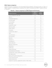
Feature (function) Local configuration with USC IPMI 2.0 Embedded diagnostics Local OS install Local updates Driver pack Shared NIC (LOM) Remote update Power control Encryption Crash screen capture1 IPv6 Auto-discovery Auto-recovery Web GUI Remote CLI ... iDRAC6) Part replacement Backup and restore configurations Virtual console (4 user) Virtual console chat Support for customer-supplied SD cards for the PowerEdge R720 and R720xd, and Dell also offers an option of iDRAC7 Express. A detailed feature comparison for iDRAC7 Enterprise and iDRAC7 Express is available for vFlash media iDRAC7...
Feature (function) Local configuration with USC IPMI 2.0 Embedded diagnostics Local OS install Local updates Driver pack Shared NIC (LOM) Remote update Power control Encryption Crash screen capture1 IPv6 Auto-discovery Auto-recovery Web GUI Remote CLI ... iDRAC6) Part replacement Backup and restore configurations Virtual console (4 user) Virtual console chat Support for customer-supplied SD cards for the PowerEdge R720 and R720xd, and Dell also offers an option of iDRAC7 Express. A detailed feature comparison for iDRAC7 Enterprise and iDRAC7 Express is available for vFlash media iDRAC7...
Technical Guide
Page 48
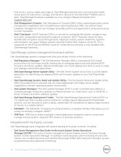
...advanced monitoring. 48 PowerEdge R720 and R720xd Technical Guide Dell servers; DMC can perform basic hardware management and can easily monitor systems anywhere within their network using ITA. Dell OpenManage easily integrates with Lifecycle Controller, as well as the BIOS, a driver, firmware and other...-based tool that includes a set of utilities for configuring and deploying Dell PowerEdge systems, and can create deployment disks as well as a no-charge software download from Symantec. Dell IT Assistant-Dell IT Assistant (ITA) is a standalone GUI-based productivity tool that...
...advanced monitoring. 48 PowerEdge R720 and R720xd Technical Guide Dell servers; DMC can perform basic hardware management and can easily monitor systems anywhere within their network using ITA. Dell OpenManage easily integrates with Lifecycle Controller, as well as the BIOS, a driver, firmware and other...-based tool that includes a set of utilities for configuring and deploying Dell PowerEdge systems, and can create deployment disks as well as a no-charge software download from Symantec. Dell IT Assistant-Dell IT Assistant (ITA) is a standalone GUI-based productivity tool that...
Glossary
Page 8
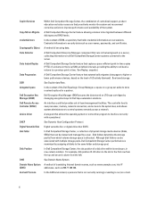
...Mirror-Migrate credential store Cryptographic Object Data Collector Data Instant Replay Data Progression DDR delegated space Dell Encryption Key Manager (EKM) Dell Remote Access Controller (DRAC) device driver DHCP Digital Versatile Disk disk folder Disk Position DNS Domain Name System (DNS) dormant Persona... Within Dell Compellent Storage Center, the combination of centralized support, product education and sales resources that ...
...Mirror-Migrate credential store Cryptographic Object Data Collector Data Instant Replay Data Progression DDR delegated space Dell Encryption Key Manager (EKM) Dell Remote Access Controller (DRAC) device driver DHCP Digital Versatile Disk disk folder Disk Position DNS Domain Name System (DNS) dormant Persona... Within Dell Compellent Storage Center, the combination of centralized support, product education and sales resources that ...


