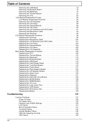
Quick Start Guide
Page 6
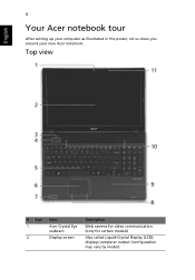
English 4 Your Acer notebook tour After setting up your computer as illustrated in the poster, let us show you around your new Acer notebook. Top view # Icon 1 2 Item Acer Crystal Eye webcam Display screen Description Web camera for video communication. (only for certain models) Also called Liquid-Crystal Display (LCD), displays computer output (configuration may vary by model).
English 4 Your Acer notebook tour After setting up your computer as illustrated in the poster, let us show you around your new Acer notebook. Top view # Icon 1 2 Item Acer Crystal Eye webcam Display screen Description Web camera for video communication. (only for certain models) Also called Liquid-Crystal Display (LCD), displays computer output (configuration may vary by model).
Quick Start Guide
Page 9
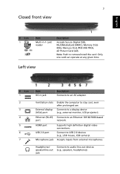
Connects to an Ethernet 10/100/1000-based port network. Ethernet (RJ-45) Connects to a display device (e.g., external monitor, LCD projector). Ventilation slots External display (VGA) port Enable the computer to audio line-out devices (e.g., speakers, headphones). Headphones/ speaker/line-out jack Connects to stay ...
Connects to an Ethernet 10/100/1000-based port network. Ethernet (RJ-45) Connects to a display device (e.g., external monitor, LCD projector). Ventilation slots External display (VGA) port Enable the computer to audio line-out devices (e.g., speakers, headphones). Headphones/ speaker/line-out jack Connects to stay ...
Quick Start Guide
Page 311
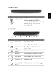
ä·Â 7 1 ÃÒ¡Òà Secure Digital (SD), MultiMediaCard (MMC), Memory Stick (MS), Memory Stick PRO (MS PRO), xD-Picture Card (xD) 1 DC-in AC 2 3 (VGA) LCD) 4 ¾ÍÃìμ Ethernet Ethernet 10/100/1000 (RJ-45) 5 ¾ÍÃìμ HDMI 6 ¾ÍÃìμ USB 2.0 USB 2.0 USB) 7 line-out
ä·Â 7 1 ÃÒ¡Òà Secure Digital (SD), MultiMediaCard (MMC), Memory Stick (MS), Memory Stick PRO (MS PRO), xD-Picture Card (xD) 1 DC-in AC 2 3 (VGA) LCD) 4 ¾ÍÃìμ Ethernet Ethernet 10/100/1000 (RJ-45) 5 ¾ÍÃìμ HDMI 6 ¾ÍÃìμ USB 2.0 USB 2.0 USB) 7 line-out
Service Guide
Page 8
... Removing the Thermal Module 81 Removing the CPU 83 LCD Module Disassembly Process 84 LCD Module Disassembly Flowchart 84 Removing the LCD Assembly 85 Removing the LCD Bezel 88 Removing the Camera Module 89 Removing the LCD Panel 90 Removing the LCD Brackets and LVDS Cable 91 Removing the Microphone Cable...Battery 135 Troubleshooting 137 Common Problems 137 Power On Issue 138 No Display Issue 139 Random Loss of BIOS Settings 140 LCD Failure 141 Built-In Keyboard Failure 141 TouchPad Failure 142 Internal Speaker Failure 142 HDD Not Operating Correctly 144 ODD Failure 145 ...
... Removing the Thermal Module 81 Removing the CPU 83 LCD Module Disassembly Process 84 LCD Module Disassembly Flowchart 84 Removing the LCD Assembly 85 Removing the LCD Bezel 88 Removing the Camera Module 89 Removing the LCD Panel 90 Removing the LCD Brackets and LVDS Cable 91 Removing the Microphone Cable...Battery 135 Troubleshooting 137 Common Problems 137 Power On Issue 138 No Display Issue 139 Random Loss of BIOS Settings 140 LCD Failure 141 Built-In Keyboard Failure 141 TouchPad Failure 142 Internal Speaker Failure 142 HDD Not Operating Correctly 144 ODD Failure 145 ...
Service Guide
Page 11
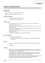
... resolution, high-brightness (200-nit) Acer CineCrystal™ LED-backlit TFT LCD 16:9 aspect ratio Graphics • ATI Radeon™ HD 4250 Graphics with 256 MB of dedicated system memory, supporting Unified Video Decoder 2 (UVD2), OpenEXR High Dynamic-Range (HDR) technology, Shader Model 4.1, Microsoft® DirectX® 10.1 (Aspire 5251/5551) • ATI Mobility...
... resolution, high-brightness (200-nit) Acer CineCrystal™ LED-backlit TFT LCD 16:9 aspect ratio Graphics • ATI Radeon™ HD 4250 Graphics with 256 MB of dedicated system memory, supporting Unified Video Decoder 2 (UVD2), OpenEXR High Dynamic-Range (HDR) technology, Shader Model 4.1, Microsoft® DirectX® 10.1 (Aspire 5251/5551) • ATI Mobility...
Service Guide
Page 16
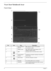
Turns the computer on and off. Touch-sensitive pointing device which functions like a computer mouse. 6 Chapter 1 Communication indicator Power button Indicates the computer's wireless connectivitoy device status. Keyboard TouchPad For entering data into your computer. Also called Liquid-Crystal Display (LCD), displays computer output. Indicates when the hard disk drive is active. Your Acer Notebook tour Front View No. 1 2 3 4 5 6 Icon Item Acer Crystal Eye webcam Display screen HDD Description Web camera for video communication (for selected models).
Turns the computer on and off. Touch-sensitive pointing device which functions like a computer mouse. 6 Chapter 1 Communication indicator Power button Indicates the computer's wireless connectivitoy device status. Keyboard TouchPad For entering data into your computer. Also called Liquid-Crystal Display (LCD), displays computer output. Indicates when the hard disk drive is active. Your Acer Notebook tour Front View No. 1 2 3 4 5 6 Icon Item Acer Crystal Eye webcam Display screen HDD Description Web camera for video communication (for selected models).

Service Guide
Page 17
... Ethernet (RJ-45) port HDMI Description Connects to an AC adapter Enable the computer to stay cool, even after prolonged use the computer. external monitor, LCD projector). The left and right buttons function like the left and right) Palmrest Speakers Microphone Indicates the computer's battery status. 1. Left and right speakers deliver...
... Ethernet (RJ-45) port HDMI Description Connects to an AC adapter Enable the computer to stay cool, even after prolonged use the computer. external monitor, LCD projector). The left and right buttons function like the left and right) Palmrest Speakers Microphone Indicates the computer's battery status. 1. Left and right speakers deliver...
Service Guide
Page 30
... VGA output support • HDMI output Support VGA Aspire 5251/5551 • All resolutions up to 2456 x 1536: 60 Hz Aspire 5551G • All resolutions up to 2048 x 1536: 85 Hz HDMI™ Aspire 5251/5551/5551G • All resolutions up to 1920 x 1080: 60 Hz LCD Display Resolutions Resolution 640x480p/60Hz 4:3 720x480p/60Hz 4:3 720x480p... 4:3 1440x576i/50Hz 16:9 1920x1080p/50Hz 16:9 2048x1536/85 Hz 16:9 2560x1440/75 Hz 16:9 Aspire 5251 Yes Yes Yes Yes Yes Yes Yes Yes Yes Yes Yes Yes Yes Yes Yes Yes Yes Aspire 5551 Yes Yes Yes Yes Yes Yes Yes Yes Yes Yes Yes Yes Yes Yes Yes Yes...
... VGA output support • HDMI output Support VGA Aspire 5251/5551 • All resolutions up to 2456 x 1536: 60 Hz Aspire 5551G • All resolutions up to 2048 x 1536: 85 Hz HDMI™ Aspire 5251/5551/5551G • All resolutions up to 1920 x 1080: 60 Hz LCD Display Resolutions Resolution 640x480p/60Hz 4:3 720x480p/60Hz 4:3 720x480p... 4:3 1440x576i/50Hz 16:9 1920x1080p/50Hz 16:9 2048x1536/85 Hz 16:9 2560x1440/75 Hz 16:9 Aspire 5251 Yes Yes Yes Yes Yes Yes Yes Yes Yes Yes Yes Yes Yes Yes Yes Yes Yes Aspire 5551 Yes Yes Yes Yes Yes Yes Yes Yes Yes Yes Yes Yes Yes Yes Yes Yes...
Service Guide
Page 31
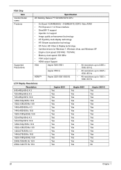
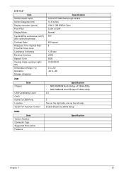
LCD 15.6" Item Vendor/model name Screen Diagonal (mm) Display resolution (pixels) Pixel Pitch Display Mode Typical White Luminance (cd/m2) (also called Brightness) Contrast Ratio ... Time) msec Luminance Uniformity Electrical Interface Support Color Viewing Angle (up/down/right/ left) Temperature Range (°C) Operating Storage (shipping) Specification AUO/CPT/CMO/Samsung/LCD/INL 15.6 inches 1366 x 768 WXGA Clare 0.204 x 0.204 Normal 220 500 typical 8 1.25 max LVDS 262K 15/35/45/45 0 to +50 -20 to...
LCD 15.6" Item Vendor/model name Screen Diagonal (mm) Display resolution (pixels) Pixel Pitch Display Mode Typical White Luminance (cd/m2) (also called Brightness) Contrast Ratio ... Time) msec Luminance Uniformity Electrical Interface Support Color Viewing Angle (up/down/right/ left) Temperature Range (°C) Operating Storage (shipping) Specification AUO/CPT/CMO/Samsung/LCD/INL 15.6 inches 1366 x 768 WXGA Clare 0.204 x 0.204 Normal 220 500 typical 8 1.25 max LVDS 262K 15/35/45/45 0 to +50 -20 to...
Service Guide
Page 55
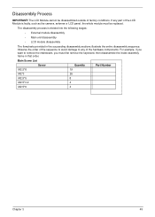
The disassembly process is faulty, such as the camera, antenna or LCD panel, the whole module must first remove the keyboard, then disassemble the inside assembly frame in the succeeding disassembly sections illustrate the entire disassembly sequence. ... List Screw Quantity Part Number M2.5*8 19 M2*3 26 M2.5*5 8 M2.5*3.2 4 M2.5*6 4 Chapter 3 45 Observe the order of the hardware components. Disassembly Process IMPORTANT: The LCD Module cannot be replaced. If any of the sequence to avoid damage to remove the mainboard, you must be disassembled outside of the...
The disassembly process is faulty, such as the camera, antenna or LCD panel, the whole module must first remove the keyboard, then disassemble the inside assembly frame in the succeeding disassembly sections illustrate the entire disassembly sequence. ... List Screw Quantity Part Number M2.5*8 19 M2*3 26 M2.5*5 8 M2.5*3.2 4 M2.5*6 4 Chapter 3 45 Observe the order of the hardware components. Disassembly Process IMPORTANT: The LCD Module cannot be replaced. If any of the sequence to avoid damage to remove the mainboard, you must be disassembled outside of the...
Service Guide
Page 87
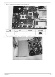
Chapter 3 77 Remove the one (1) securing screw from the Mainboard. Step Mainboard Size M2.5*5 Quantity 1 Screw Type 5. Place a dust free, protective mat on the lcd screen to aid in the removal of the mainboard. 4.
Chapter 3 77 Remove the one (1) securing screw from the Mainboard. Step Mainboard Size M2.5*5 Quantity 1 Screw Type 5. Place a dust free, protective mat on the lcd screen to aid in the removal of the mainboard. 4.
Service Guide
Page 94
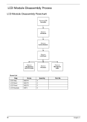
LCD Module Disassembly Process LCD Module Disassembly Flowchart Remove LCD Assembly Remove LCD Bezel Remove Camera Module Remove LCD Panel Remove LCD Brackets and FPC Cable Remove Antennas Screw List Step LCD Assy LCD Bezel LCD Panel LCD Brackets Screw M2.5*5 M2.5*6 M2.5*5 M2*3 Quantity 4 2 2 6 Remove Microphone Cable Part No. 84 Chapter 3
LCD Module Disassembly Process LCD Module Disassembly Flowchart Remove LCD Assembly Remove LCD Bezel Remove Camera Module Remove LCD Panel Remove LCD Brackets and FPC Cable Remove Antennas Screw List Step LCD Assy LCD Bezel LCD Panel LCD Brackets Screw M2.5*5 M2.5*6 M2.5*5 M2*3 Quantity 4 2 2 6 Remove Microphone Cable Part No. 84 Chapter 3
Service Guide
Page 95
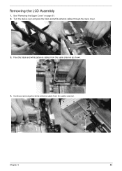
See "Removing the Upper Cover" on page 61. 2. Chapter 3 85 Continue removing the white antenna cable from the cable channel as shown. 4. Removing the LCD Assembly 1. Turn the device over and pass the black and white antenna cables through the lower cover. 3. Free the black and white antenna cables from the cable channel.
See "Removing the Upper Cover" on page 61. 2. Chapter 3 85 Continue removing the white antenna cable from the cable channel as shown. 4. Removing the LCD Assembly 1. Turn the device over and pass the black and white antenna cables through the lower cover. 3. Free the black and white antenna cables from the cable channel.
Service Guide
Page 97
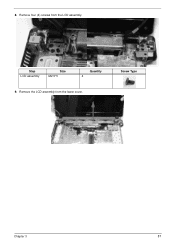
Remove the LCD assembly from the LCD assembly. Screw Type Chapter 3 87 Step LCD assembly Size M2.5*5 Quantity 4 9. 8. Remove four (4) screws from the lower cover.
Remove the LCD assembly from the LCD assembly. Screw Type Chapter 3 87 Step LCD assembly Size M2.5*5 Quantity 4 9. 8. Remove four (4) screws from the lower cover.
Service Guide
Page 98
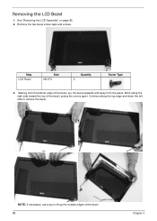
See "Removing the LCD Assembly" on page 85. 2. Work along the top edge and down the left side to lift up the outside edges of the bezel. 88 Chapter 3 Removing the LCD Bezel 1. Step LCD Bezel Size M2.5*6 Quantity 2 Screw Type 3. Starting from the bottom edge of the bezel, prying the covers apart. Remove the two bezel screw caps and screws. Continue along the right side toward the top of the bezel, pry the bezel upwards and away from the panel. NOTE: If necessary, use a pry to remove the bezel.
See "Removing the LCD Assembly" on page 85. 2. Work along the top edge and down the left side to lift up the outside edges of the bezel. 88 Chapter 3 Removing the LCD Bezel 1. Step LCD Bezel Size M2.5*6 Quantity 2 Screw Type 3. Starting from the bottom edge of the bezel, prying the covers apart. Remove the two bezel screw caps and screws. Continue along the right side toward the top of the bezel, pry the bezel upwards and away from the panel. NOTE: If necessary, use a pry to remove the bezel.
Service Guide
Page 99
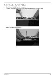
Chapter 3 89 See "Removing the LCD Assembly" on page 85. 2. Remove the Camera from the module. Removing the Camera Module 1. Locate the Camera Module at the top of the LCD Module and disconnect the camera cable. 3.
Chapter 3 89 See "Removing the LCD Assembly" on page 85. 2. Remove the Camera from the module. Removing the Camera Module 1. Locate the Camera Module at the top of the LCD Module and disconnect the camera cable. 3.
Service Guide
Page 100
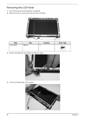
Remove the adhesive strip holding the cables in place. Removing the LCD Panel 1. Screw Type 4. Step LCD Panel Size M2.5*5 Quantity 4 3. See "Removing the Camera Module" on page 89. 2. Lift the LCD Panel clear of the module. 90 Chapter 3 Remove the four (4) securing screws from the LCD Panel.
Remove the adhesive strip holding the cables in place. Removing the LCD Panel 1. Screw Type 4. Step LCD Panel Size M2.5*5 Quantity 4 3. See "Removing the Camera Module" on page 89. 2. Lift the LCD Panel clear of the module. 90 Chapter 3 Remove the four (4) securing screws from the LCD Panel.
Service Guide
Page 101
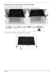
Removing the LCD Brackets and LVDS Cable 1. Step LCD Brackets Size M2*3 Quantity 6 3. Screw Type Chapter 3 91 Remove the LCD brackets by pulling away from the LCD Panel brackets. Remove the six (6) securing screws (three on page 90. 2. See "Removing the LCD Panel" on each side) from the LCD Panel.
Removing the LCD Brackets and LVDS Cable 1. Step LCD Brackets Size M2*3 Quantity 6 3. Screw Type Chapter 3 91 Remove the LCD brackets by pulling away from the LCD Panel brackets. Remove the six (6) securing screws (three on page 90. 2. See "Removing the LCD Panel" on each side) from the LCD Panel.
Service Guide
Page 102
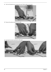
Pull the cable up as shown. 5. Remove the adhesive tape from the cable. 6. 4. Peel back the mylar securing the LVDS cable. 92 Chapter 3 Turn the LCD panel over to expose the rear.
Pull the cable up as shown. 5. Remove the adhesive tape from the cable. 6. 4. Peel back the mylar securing the LVDS cable. 92 Chapter 3 Turn the LCD panel over to expose the rear.
Service Guide
Page 104
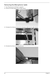
Remove the cable bundle from the cable channel. 4. Peel back the foil tabs and remove the microphone cable from the hinge channel. 3. Peel back the foil tab on page 90. 2. Removing the Microphone Cable 1. See "Removing the LCD Panel" on the microphone set. 94 Chapter 3
Remove the cable bundle from the cable channel. 4. Peel back the foil tabs and remove the microphone cable from the hinge channel. 3. Peel back the foil tab on page 90. 2. Removing the Microphone Cable 1. See "Removing the LCD Panel" on the microphone set. 94 Chapter 3


