Service Guide
Page 7
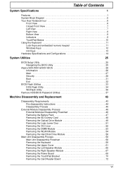
Table of Contents System Specifications 1 Features 1 System Block Diagram 5 Your Acer Notebook tour 6 Front View 6 Closed Front View 7 Left View 7 Right View 8 Bottom View 9 Indicators 9 TouchPad Basics 10 Using the Keyboard... 25 Aspire 5251/5551G/5551 BIOS 26 Information 26 Main 27 Security 28 Boot 31 Exit 32 BIOS Flash Utilities 33 DOS Flash Utility 34 WinFlash Utility 36 Remove HDD/BIOS Password Utilities 37 Machine Disassembly and Replacement 43 Disassembly Requirements 43 Pre-disassembly Instructions 44 Disassembly Process 45 External Module Disassembly Process...
Table of Contents System Specifications 1 Features 1 System Block Diagram 5 Your Acer Notebook tour 6 Front View 6 Closed Front View 7 Left View 7 Right View 8 Bottom View 9 Indicators 9 TouchPad Basics 10 Using the Keyboard... 25 Aspire 5251/5551G/5551 BIOS 26 Information 26 Main 27 Security 28 Boot 31 Exit 32 BIOS Flash Utilities 33 DOS Flash Utility 34 WinFlash Utility 36 Remove HDD/BIOS Password Utilities 37 Machine Disassembly and Replacement 43 Disassembly Requirements 43 Pre-disassembly Instructions 44 Disassembly Process 45 External Module Disassembly Process...
Service Guide
Page 54
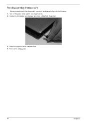
Place the system on a flat, stable surface. 4. Unplug the AC adapter and all peripherals. 2. Pre-disassembly Instructions Before proceeding with the disassembly procedure, make sure that you do the following: 1. Remove the battery pack. 44 Chapter 3 Turn off the power to the system and all power and signal cables from the system. 3.
Place the system on a flat, stable surface. 4. Unplug the AC adapter and all peripherals. 2. Pre-disassembly Instructions Before proceeding with the disassembly procedure, make sure that you do the following: 1. Remove the battery pack. 44 Chapter 3 Turn off the power to the system and all power and signal cables from the system. 3.
Service Guide
Page 56
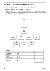
... The flowchart below gives you a graphic representation of the external module disassembly sequence and instructs you must first remove the switch board. Turn off system and peripherals power Disconnect power and signal cables from the mass produced model. For example..., if you want to remove the keyboard, you on the components that need to be removed during servicing. External Module Disassembly Process IMPORTANT: ...
... The flowchart below gives you a graphic representation of the external module disassembly sequence and instructs you must first remove the switch board. Turn off system and peripherals power Disconnect power and signal cables from the mass produced model. For example..., if you want to remove the keyboard, you on the components that need to be removed during servicing. External Module Disassembly Process IMPORTANT: ...
Service Guide
Page 150
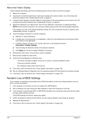
... resolved, see "Online Support Information" on battery alone as this may be defective and should be replaced. See the User Manual for instructions on page 45. 5. Click Apply and check the display. If the Issue is faulty and should be replaced. Replace the Motherboard. ...6. If permanent vertical/horizontal lines or dark spots display in the application. See "Disassembly Process" on page 45. 3. e. Roll back the video driver to correct the problem. 1. If the computer is faulty and should be ...
... resolved, see "Online Support Information" on battery alone as this may be defective and should be replaced. See the User Manual for instructions on page 45. 5. Click Apply and check the display. If the Issue is faulty and should be replaced. Replace the Motherboard. ...6. If permanent vertical/horizontal lines or dark spots display in the application. See "Disassembly Process" on page 45. 3. e. Roll back the video driver to correct the problem. 1. If the computer is faulty and should be ...


