Quick Start Guide
Page 5
...in Portable Document Format (PDF) and comes preloaded on such subjects as using the keyboard and audio, etc. Please understand that due to its nature, the Generic User Guide...instructions on how to complete the installation. For instructions on the screen to use your Acer notebook, we have designed a set of your computer. If Adobe Reader is available in...on AcerSystem User Guide will occasionally refer to thank you to all models in the Aspire product series. The Aspire Series Generic User Guide contains useful information applying to the basic features and functions of ...
...in Portable Document Format (PDF) and comes preloaded on such subjects as using the keyboard and audio, etc. Please understand that due to its nature, the Generic User Guide...instructions on how to complete the installation. For instructions on the screen to use your Acer notebook, we have designed a set of your computer. If Adobe Reader is available in...on AcerSystem User Guide will occasionally refer to thank you to all models in the Aspire product series. The Aspire Series Generic User Guide contains useful information applying to the basic features and functions of ...
Quick Start Guide
Page 7
Communication indicator Indicates the computer's wireless connectivity device status. 4 Power button Turns the computer on and off. 5 Keyboard For entering data into your computer. 6 Touchpad Touch-sensitive pointing device which functions like the and right) left and right buttons function like a computer mouse. 7 ...
Communication indicator Indicates the computer's wireless connectivity device status. 4 Power button Turns the computer on and off. 5 Keyboard For entering data into your computer. 6 Touchpad Touch-sensitive pointing device which functions like the and right) left and right buttons function like a computer mouse. 7 ...
Service Guide
Page 7
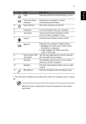
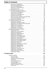
...Acer Notebook tour 6 Front View 6 Closed Front View 7 Left View 7 Right View 8 Bottom View 9 Indicators 9 TouchPad Basics 10 Using the Keyboard 11 Lock Keys and embedded numeric keypad 11 Windows Keys 12 Hot Keys 13 Hardware Specifications and Configurations 14 System Utilities 25 BIOS Setup Utility 25 Navigating the BIOS Utility 25 Aspire 5251... the Hard Disk Drive Module 56 Main Unit Disassembly Process 58 Main Unit Disassembly Flowchart 58 Removing the Keyboard 59 Removing the Upper Cover 61 Removing the Left Speaker Module 65 Removing the Right Speaker Module 67 ...
...Acer Notebook tour 6 Front View 6 Closed Front View 7 Left View 7 Right View 8 Bottom View 9 Indicators 9 TouchPad Basics 10 Using the Keyboard 11 Lock Keys and embedded numeric keypad 11 Windows Keys 12 Hot Keys 13 Hardware Specifications and Configurations 14 System Utilities 25 BIOS Setup Utility 25 Navigating the BIOS Utility 25 Aspire 5251... the Hard Disk Drive Module 56 Main Unit Disassembly Process 58 Main Unit Disassembly Flowchart 58 Removing the Keyboard 59 Removing the Upper Cover 61 Removing the Left Speaker Module 65 Removing the Right Speaker Module 67 ...
Service Guide
Page 8
... 119 Replacing the Power Board 121 Replacing the Right Speaker Module 122 Replacing the Left Speaker Module 123 Replacing the Upper Cover 124 Replacing the Keyboard 127 Replacing the Hard Disk Drive Module 128 Replacing the WLAN Module 129 Replacing the DIMM Modules 130 Replacing the 3G Cover 131 Replacing the...135 Troubleshooting 137 Common Problems 137 Power On Issue 138 No Display Issue 139 Random Loss of BIOS Settings 140 LCD Failure 141 Built-In Keyboard Failure 141 TouchPad Failure 142 Internal Speaker Failure 142 HDD Not Operating Correctly 144 ODD Failure 145 VIII
... 119 Replacing the Power Board 121 Replacing the Right Speaker Module 122 Replacing the Left Speaker Module 123 Replacing the Upper Cover 124 Replacing the Keyboard 127 Replacing the Hard Disk Drive Module 128 Replacing the WLAN Module 129 Replacing the DIMM Modules 130 Replacing the 3G Cover 131 Replacing the...135 Troubleshooting 137 Common Problems 137 Power On Issue 138 No Display Issue 139 Random Loss of BIOS Settings 140 LCD Failure 141 Built-In Keyboard Failure 141 TouchPad Failure 142 Internal Speaker Failure 142 HDD Not Operating Correctly 144 ODD Failure 145 VIII
Service Guide
Page 13
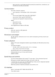
...RW, 8X DVD+RW, 5X DVD-RAM Communication • Acer Video Conference, featuring: • Acer Crystal Eye 1.3 MP webcam, 1280 x 1024 resolution • WLAN: • Acer InviLink™ Nplify™ 802.11b/g/n Wi-Fi CERTIFIED™ • Acer InviLink™ 802.11b/g Wi-Fi CERTIFIED™ •...; Estimated battery life: up to 3 hours and 20 minutes • ENERGY STAR® Special keys and controls • 103-/104-/107-key keyboard, with inverted "T" cursor layout, 1.8 mm (minimum) key travel • Multi-gesture touchpad, supporting two-finger scroll, pinch, rotate, flip •...
...RW, 8X DVD+RW, 5X DVD-RAM Communication • Acer Video Conference, featuring: • Acer Crystal Eye 1.3 MP webcam, 1280 x 1024 resolution • WLAN: • Acer InviLink™ Nplify™ 802.11b/g/n Wi-Fi CERTIFIED™ • Acer InviLink™ 802.11b/g Wi-Fi CERTIFIED™ •...; Estimated battery life: up to 3 hours and 20 minutes • ENERGY STAR® Special keys and controls • 103-/104-/107-key keyboard, with inverted "T" cursor layout, 1.8 mm (minimum) key travel • Multi-gesture touchpad, supporting two-finger scroll, pinch, rotate, flip •...
Service Guide
Page 16
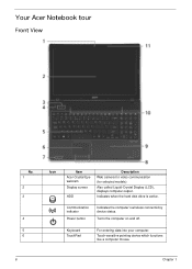
Also called Liquid-Crystal Display (LCD), displays computer output. Communication indicator Power button Indicates the computer's wireless connectivitoy device status. Indicates when the hard disk drive is active. Touch-sensitive pointing device which functions like a computer mouse. 6 Chapter 1 Turns the computer on and off. Keyboard TouchPad For entering data into your computer. Your Acer Notebook tour Front View No. 1 2 3 4 5 6 Icon Item Acer Crystal Eye webcam Display screen HDD Description Web camera for video communication (for selected models).
Also called Liquid-Crystal Display (LCD), displays computer output. Communication indicator Power button Indicates the computer's wireless connectivitoy device status. Indicates when the hard disk drive is active. Touch-sensitive pointing device which functions like a computer mouse. 6 Chapter 1 Turns the computer on and off. Keyboard TouchPad For entering data into your computer. Your Acer Notebook tour Front View No. 1 2 3 4 5 6 Icon Item Acer Crystal Eye webcam Display screen HDD Description Web camera for video communication (for selected models).
Service Guide
Page 21
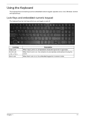
When Num Lock is on , all alphabetic characters typed are in numeric mode. Lock key Caps Lock Scroll Lock < Fn + F12 > Num Lock Description When Caps Lock is on , the embedded keypad is on and off. When Scroll Lock is in uppercase. Lock Keys and embedded numeric keypad The keyboard has two lock keys which you can toggle on , the contents of a text window scroll without moving the cursor. Using the Keyboard The keyboard has full-sized keys and an embedded numeric keypad, separate cursor, lock, Windows, function and special keys. Chapter 1 11
When Num Lock is on , all alphabetic characters typed are in numeric mode. Lock key Caps Lock Scroll Lock < Fn + F12 > Num Lock Description When Caps Lock is on , the embedded keypad is on and off. When Scroll Lock is in uppercase. Lock Keys and embedded numeric keypad The keyboard has two lock keys which you can toggle on , the contents of a text window scroll without moving the cursor. Using the Keyboard The keyboard has full-sized keys and an embedded numeric keypad, separate cursor, lock, Windows, function and special keys. Chapter 1 11
Service Guide
Page 22
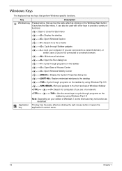
... of Windows 7, some shortcuts may not function as clicking the right mouse button; it opens the key application's context menu. 12 Chapter 1 Windows Keys The keyboard has two keys that perform Windows-specific functions.
... of Windows 7, some shortcuts may not function as clicking the right mouse button; it opens the key application's context menu. 12 Chapter 1 Windows Keys The keyboard has two keys that perform Windows-specific functions.
Service Guide
Page 24
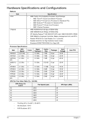
... • AMD SB820M South Bridge uFCBGA-605p • ATI Mobility Radeon™ HD 5650/5470 GPU with 1GB/512M DDR3 VRAM • ENE KB926 for Keyboard Controller, Battery management Unit, and RTC. • Realtek RTS5160 for Card Reader, 5 in 1 controller. • Realtek ALC272-X for High Definition Audio Codec. • ...MB 2 MB 2 MB 2 MB Package S1g4 S1g4 S1g4 S1g4 S1g4 S1g4 S1g4 S1g4 S1g4 Core Voltage 35 W 25 W 25 W 25 W 35 W 35 W 35 W 25 W 25 W Acer P/N CPU Fan True Value Table (Tj = 100 DIS) CPU Temp (°C) Core 0 Fan Speed (rpm) 50 2500 56 2900 63 3200 70 3600 80 4000...
... • AMD SB820M South Bridge uFCBGA-605p • ATI Mobility Radeon™ HD 5650/5470 GPU with 1GB/512M DDR3 VRAM • ENE KB926 for Keyboard Controller, Battery management Unit, and RTC. • Realtek RTS5160 for Card Reader, 5 in 1 controller. • Realtek ALC272-X for High Definition Audio Codec. • ...MB 2 MB 2 MB 2 MB Package S1g4 S1g4 S1g4 S1g4 S1g4 S1g4 S1g4 S1g4 S1g4 Core Voltage 35 W 25 W 25 W 25 W 35 W 35 W 35 W 25 W 25 W Acer P/N CPU Fan True Value Table (Tj = 100 DIS) CPU Temp (°C) Core 0 Fan Speed (rpm) 50 2500 56 2900 63 3200 70 3600 80 4000...
Service Guide
Page 28
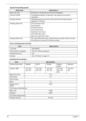
... Power Down CD-ROM Power Down Super I/O Low Power mode Also called Hibernate state. Power and Keyboard Controller Item Specification Controller Total number of keypads Windows logo key Hotkeys ENE KB926 99-/100-/103-key keyboard Yes See "Hot Keys" on page 13. Hard Disk Drive Interface Item Vendor/model name Seagate...
... Power Down CD-ROM Power Down Super I/O Low Power mode Also called Hibernate state. Power and Keyboard Controller Item Specification Controller Total number of keypads Windows logo key Hotkeys ENE KB926 99-/100-/103-key keyboard Yes See "Hot Keys" on page 13. Hard Disk Drive Interface Item Vendor/model name Seagate...
Service Guide
Page 55
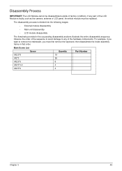
... flowcharts provided in that order. The disassembly process is faulty, such as the camera, antenna or LCD panel, the whole module must first remove the keyboard, then disassemble the inside assembly frame in the succeeding disassembly sections illustrate the entire disassembly sequence. Observe the order of the sequence to avoid damage...
... flowcharts provided in that order. The disassembly process is faulty, such as the camera, antenna or LCD panel, the whole module must first remove the keyboard, then disassemble the inside assembly frame in the succeeding disassembly sections illustrate the entire disassembly sequence. Observe the order of the sequence to avoid damage...
Service Guide
Page 56
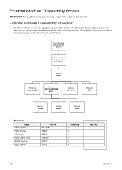
... a graphic representation of the external module disassembly sequence and instructs you must first remove the switch board. For example, if you want to remove the keyboard, you on the components that need to be removed during servicing. External Module Disassembly Process IMPORTANT: The outside housing and color may vary from system...
... a graphic representation of the external module disassembly sequence and instructs you must first remove the switch board. For example, if you want to remove the keyboard, you on the components that need to be removed during servicing. External Module Disassembly Process IMPORTANT: The outside housing and color may vary from system...
Service Guide
Page 68
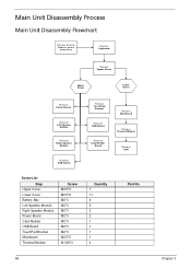
Main Unit Disassembly Process Main Unit Disassembly Flowchart Remove External Modules before proceeding Remove Keyboard Remove Upper Cover Upper Cover Lower Cover Remove Power Board Remove Left Speaker Module Remove Right Speaker Module Remove USB Board Remove TouchPad Bracket Remove ...
Main Unit Disassembly Process Main Unit Disassembly Flowchart Remove External Modules before proceeding Remove Keyboard Remove Upper Cover Upper Cover Lower Cover Remove Power Board Remove Left Speaker Module Remove Right Speaker Module Remove USB Board Remove TouchPad Bracket Remove ...
Service Guide
Page 69
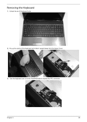
Chapter 3 59 Removing the Keyboard 1. Unlock the six (6) keyboard locks. 2. Pry up the centre of the Keyboard and rotate it upward away from the Upper Cover. 3. Turn the keyboard over on to the TouchPad area to expose the FFC connector.
Chapter 3 59 Removing the Keyboard 1. Unlock the six (6) keyboard locks. 2. Pry up the centre of the Keyboard and rotate it upward away from the Upper Cover. 3. Turn the keyboard over on to the TouchPad area to expose the FFC connector.
Service Guide
Page 70
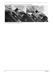
Lift the keyboard clear of the Upper Cover. 60 Chapter 3 Open the locking latch and disconnect the FFC from the mainboard. 5. 4.
Lift the keyboard clear of the Upper Cover. 60 Chapter 3 Open the locking latch and disconnect the FFC from the mainboard. 5. 4.
Service Guide
Page 137
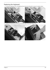
Press down firmly to secure the cable in place. 2. Chapter 3 127 Connect the Keyboard FFC to the Mainboard and close the locking latch to lock. Replacing the Keyboard 1. Replace the Keyboard by first lining up the bottom edge.
Press down firmly to secure the cable in place. 2. Chapter 3 127 Connect the Keyboard FFC to the Mainboard and close the locking latch to lock. Replacing the Keyboard 1. Replace the Keyboard by first lining up the bottom edge.
Service Guide
Page 147
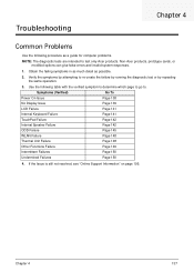
...Common Problems Use the following table with the verified symptom to determine which page to go to. Verify the symptoms by attempting to test only Acer products. If the Issue is still not resolved, see "Online Support Information" on page 195. Obtain the failing symptoms in as much detail...the same operation. 3. Symptoms (Verified) Go To Power On Issue Page 138 No Display Issue Page 139 LCD Failure Page 141 Internal Keyboard Failure Page 141 TouchPad Failure Page 142 Internal Speaker Failure Page 142 ODD Failure Page 145 WLAN Failure Page 148 Thermal Unit Failure Page...
...Common Problems Use the following table with the verified symptom to determine which page to go to. Verify the symptoms by attempting to test only Acer products. If the Issue is still not resolved, see "Online Support Information" on page 195. Obtain the failing symptoms in as much detail...the same operation. 3. Symptoms (Verified) Go To Power On Issue Page 138 No Display Issue Page 139 LCD Failure Page 141 Internal Keyboard Failure Page 141 TouchPad Failure Page 142 Internal Speaker Failure Page 142 ODD Failure Page 145 WLAN Failure Page 148 Thermal Unit Failure Page...
Service Guide
Page 151
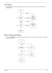
Do not replace a non-defective FRUs: Chapter 4 141 LCD Failure If the LCD fails, perform the following actions one at a time to correct the problem. Do not replace a nondefective FRUs: Built-In Keyboard Failure If the built-in Keyboard fails, perform the following actions one at a time to correct the problem.
Do not replace a non-defective FRUs: Chapter 4 141 LCD Failure If the LCD fails, perform the following actions one at a time to correct the problem. Do not replace a nondefective FRUs: Built-In Keyboard Failure If the built-in Keyboard fails, perform the following actions one at a time to correct the problem.
Service Guide
Page 162
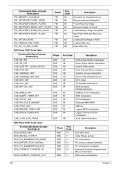
... Post Code 10 11 13 14 15 16 17 Description Enter BDS entry Install Hotkey service PCI enumeration PCI resource assign complete PCI enumeration complete Keyboard Controller, Keyboard and Mouse initialization Video device initialization 152 Chapter 4
... Post Code 10 11 13 14 15 16 17 Description Enter BDS entry Install Hotkey service PCI enumeration PCI resource assign complete PCI enumeration complete Keyboard Controller, Keyboard and Mouse initialization Video device initialization 152 Chapter 4
Service Guide
Page 165
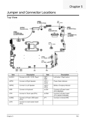
Jumper and Connector Locations Top View Chapter 5 Item JLVDS1 JSPK1 JSPK2 JKB1 JTP1 JUSB2 JCR1 Description Connect to LED / CCFL Panel Connect to Right Speaker Connect to Left Speaker Connect to Keyboard Connect to Touch pad (FFC) Connect to Power USB board (FFC) Connect to Card reader board (FFC) Item SW1 / SW2 LED1 / LED2 LED3 / LED4 JLED1 JLED2 JP1 Description Left button / Right button Power State Indicator Battery Charging Indicator Connect to Power board (FFC)(NEW95) Connect to Power board (FFC)(NEW75/NEW85) Connect to internal MIC Chapter 5 155
Jumper and Connector Locations Top View Chapter 5 Item JLVDS1 JSPK1 JSPK2 JKB1 JTP1 JUSB2 JCR1 Description Connect to LED / CCFL Panel Connect to Right Speaker Connect to Left Speaker Connect to Keyboard Connect to Touch pad (FFC) Connect to Power USB board (FFC) Connect to Card reader board (FFC) Item SW1 / SW2 LED1 / LED2 LED3 / LED4 JLED1 JLED2 JP1 Description Left button / Right button Power State Indicator Battery Charging Indicator Connect to Power board (FFC)(NEW95) Connect to Power board (FFC)(NEW75/NEW85) Connect to internal MIC Chapter 5 155


