Quick Start Guide
Page 9
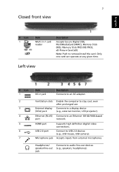
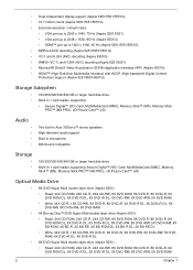
Only one card can operate at any given time. Left view # Icon 1 2 3 4 5 6 7 Item DC-in -1 card reader Description Accepts Secure Digital (SD), MultiMediaCard (MMC), Memory Stick (MS), Memory Stick PRO (MS PRO), xD-Picture Card (xD). Ethernet (RJ-45) Connects to an AC adapter. HDMI port USB 2.0 port Microphone jack Supports high definition...
Only one card can operate at any given time. Left view # Icon 1 2 3 4 5 6 7 Item DC-in -1 card reader Description Accepts Secure Digital (SD), MultiMediaCard (MMC), Memory Stick (MS), Memory Stick PRO (MS PRO), xD-Picture Card (xD). Ethernet (RJ-45) Connects to an AC adapter. HDMI port USB 2.0 port Microphone jack Supports high definition...
Quick Start Guide
Page 11
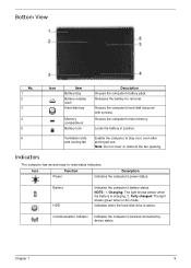
... cool, even after prolonged use. 9 Base view English # Icon 1 2 3 4 5 6 Item Battery bay Battery release latch Hard disk bay Memory compartment Battery lock Description Houses the computer's battery pack. Houses the computer's main memory. Locks the battery in position. Ventilation slots and cooling fan Enable the computer to 80% Releases the battery for...
... cool, even after prolonged use. 9 Base view English # Icon 1 2 3 4 5 6 Item Battery bay Battery release latch Hard disk bay Memory compartment Battery lock Description Houses the computer's battery pack. Houses the computer's main memory. Locks the battery in position. Ventilation slots and cooling fan Enable the computer to 80% Releases the battery for...
Quick Start Guide
Page 311
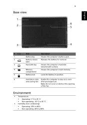
ä·Â 7 1 ÃÒ¡Òà Secure Digital (SD), MultiMediaCard (MMC), Memory Stick (MS), Memory Stick PRO (MS PRO), xD-Picture Card (xD) 1 DC-in AC 2 3 (VGA) LCD) 4 ¾ÍÃìμ Ethernet Ethernet 10/100/1000 (RJ-45) 5 ¾ÍÃìμ HDMI 6 ¾ÍÃìμ USB 2.0 USB 2.0 USB) 7 line-out
ä·Â 7 1 ÃÒ¡Òà Secure Digital (SD), MultiMediaCard (MMC), Memory Stick (MS), Memory Stick PRO (MS PRO), xD-Picture Card (xD) 1 DC-in AC 2 3 (VGA) LCD) 4 ¾ÍÃìμ Ethernet Ethernet 10/100/1000 (RJ-45) 5 ¾ÍÃìμ HDMI 6 ¾ÍÃìμ USB 2.0 USB 2.0 USB) 7 line-out
Service Guide
Page 5
... to the BASIC CONFIGURATION decided for Acer's "global" product offering. These LOCALIZED FEATURES will not be covered in this printed Service Guide. This Service Guide provides you with further technical details. 2. If, ... responsible personnel/channel to provide you should check the most up-to-date information available on card, modem, or extra memory capability). You MUST use the list provided by your Acer office may have decided to those given in the printed Service Guide. To better fit local market requirements and enhance product...
... to the BASIC CONFIGURATION decided for Acer's "global" product offering. These LOCALIZED FEATURES will not be covered in this printed Service Guide. This Service Guide provides you with further technical details. 2. If, ... responsible personnel/channel to provide you should check the most up-to-date information available on card, modem, or extra memory capability). You MUST use the list provided by your Acer office may have decided to those given in the printed Service Guide. To better fit local market requirements and enhance product...
Service Guide
Page 11
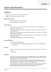
... RS880M and SB820M Chipset (Aspire 5251/5551/5551G) System Memory • Dual-channel DDR3 SDRAM support: • Up to 4 GB of DDR3 1066 MHz memory, upgradeable to 8 GB using two soDIMM modules (for 64-bit OS) Display • • 15.6" HD 1366 x 768 pixel resolution, high-brightness (200-nit) Acer CineCrystal™ LED-backlit TFT...
... RS880M and SB820M Chipset (Aspire 5251/5551/5551G) System Memory • Dual-channel DDR3 SDRAM support: • Up to 4 GB of DDR3 1066 MHz memory, upgradeable to 8 GB using two soDIMM modules (for 64-bit OS) Display • • 15.6" HD 1366 x 768 pixel resolution, high-brightness (200-nit) Acer CineCrystal™ LED-backlit TFT...
Service Guide
Page 12
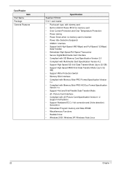
...Aspire 5251/5551/5551G) Storage Subsystem • 160/250/320/500/640 GB or larger hard disk drive • Multi-in-1 card reader, supporting: • Secure Digital™ (SD) Card, MultiMediaCard (MMC), Memory Stick™ (MS), Memory Stick PRO™ (MS PRO), xD-Picture Card™ (xD) Audio Two built-in Acer... supporting Secure Digital™ (SD) Card, MultiMediaCard (MMC), Memory Stick™ (MS), Memory Stick PRO™ (MS PRO), xD-Picture Card™ (xD) Optical Media Drive • 8X DVD-Super Multi double-layer drive (Aspire 5251): • Read: 24X CD-ROM, 24X CD-R, 24X ...
...Aspire 5251/5551/5551G) Storage Subsystem • 160/250/320/500/640 GB or larger hard disk drive • Multi-in-1 card reader, supporting: • Secure Digital™ (SD) Card, MultiMediaCard (MMC), Memory Stick™ (MS), Memory Stick PRO™ (MS PRO), xD-Picture Card™ (xD) Audio Two built-in Acer... supporting Secure Digital™ (SD) Card, MultiMediaCard (MMC), Memory Stick™ (MS), Memory Stick PRO™ (MS PRO), xD-Picture Card™ (xD) Optical Media Drive • 8X DVD-Super Multi double-layer drive (Aspire 5251): • Read: 24X CD-ROM, 24X CD-R, 24X ...

Service Guide
Page 17
... and right speakers deliver stereo audio output. Fully charged: The light shows blue when in -1 card reader Description Accepts Secure Digital (SD), MultiMediaCard (MMC), Memory Stick (MS), Memory Stick PRO (MS PRO), xDPicture Card (xD). Connects to HDMI devices 7 external monitor, LCD projector). No. 7 8 9 10 11 Icon Item Power1 Description Indicates the...
... and right speakers deliver stereo audio output. Fully charged: The light shows blue when in -1 card reader Description Accepts Secure Digital (SD), MultiMediaCard (MMC), Memory Stick (MS), Memory Stick PRO (MS PRO), xDPicture Card (xD). Connects to HDMI devices 7 external monitor, LCD projector). No. 7 8 9 10 11 Icon Item Power1 Description Indicates the...
Service Guide
Page 19
... computer's battery status. Locks the battery in AC mode. Indicates when the hard disk drive is charging. 2. Houses the computer's main memory. Charging: The light shows amber when the battery is active. Communication indicator Indicates the computer's wireless connectivitoy device status. Chapter 1 9 ... obstruct the fan opening. Bottom View No. 1 2 3 4 5 Icon Item Battery bay Battery release latch Hard disk bay Memory compartment Battery lock Description Houses the computer's battery pack. Houses the computer's hard disk (secured with screws). NOTE: 1.
... computer's battery status. Locks the battery in AC mode. Indicates when the hard disk drive is charging. 2. Houses the computer's main memory. Charging: The light shows amber when the battery is active. Communication indicator Indicates the computer's wireless connectivitoy device status. Chapter 1 9 ... obstruct the fan opening. Bottom View No. 1 2 3 4 5 Icon Item Battery bay Battery release latch Hard disk bay Memory compartment Battery lock Description Houses the computer's battery pack. Houses the computer's hard disk (secured with screws). NOTE: 1.
Service Guide
Page 26
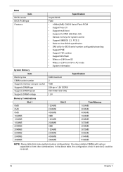
... 8192MB NOTE: Above table lists some system memory configurations. In the above table, the configuration of slot 1 and slot 2 could be reversed. 16 Chapter 1 BIOS Item BIOS vendor BIOS ROM type Features Specification Insyde BIOS Flash • 16Mbit(2MB) CMOS Serial Flash ROM • Support Acer UI • Support multi-boot •...
... 8192MB NOTE: Above table lists some system memory configurations. In the above table, the configuration of slot 1 and slot 2 could be reversed. 16 Chapter 1 BIOS Item BIOS vendor BIOS ROM type Features Specification Insyde BIOS Flash • 16Mbit(2MB) CMOS Serial Flash ROM • Support Acer UI • Support multi-boot •...
Service Guide
Page 27
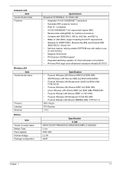
..., Ethernet-like MIB, and Ethernet MIB (IEEE 802.3z, Clause 30) • Self-boot feature, utilizing smaller EEPROM size with ability to use on-chip memory • Supports iSCSI boott • PCI Express CLKREQ support • Integrated switching regulator for improved power consumption • IPv4 and IPv6 large send offload and...
..., Ethernet-like MIB, and Ethernet MIB (IEEE 802.3z, Clause 30) • Self-boot feature, utilizing smaller EEPROM size with ability to use on-chip memory • Supports iSCSI boott • PCI Express CLKREQ support • Integrated switching regulator for improved power consumption • IPv4 and IPv6 large send offload and...
Service Guide
Page 29
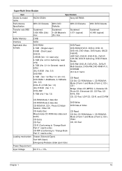
..., DVD-R MultiBorder, DVD-RW, DVD+R, DVD+R DL, DVD+R Multi-Session, DVD+RW, DVD-RAM V1.0, DVDRAM V2.0 & 2.1 &2.2. Sustained: 1,571 (typical) Sustained: 10,993 (typical) Buffer Memory 2 MB Interface SATA Applicable disc formats DVD-ROM: 4.7GB (Single Layer) 8.5GB (Dual Layer) DVD-R: 3.95GB (Ver. 1.0: read only) 4.7GB (Ver. 2.0 for Authoring: read only...
..., DVD-R MultiBorder, DVD-RW, DVD+R, DVD+R DL, DVD+R Multi-Session, DVD+RW, DVD-RAM V1.0, DVDRAM V2.0 & 2.1 &2.2. Sustained: 1,571 (typical) Sustained: 10,993 (typical) Buffer Memory 2 MB Interface SATA Applicable disc formats DVD-ROM: 4.7GB (Single Layer) 8.5GB (Dual Layer) DVD-R: 3.95GB (Ver. 1.0: read only) 4.7GB (Ver. 2.0 for Authoring: read only...
Service Guide
Page 30
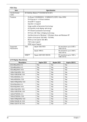
...and Windows XP • Engine clock speed: 550 MHz / 750 MHz • Memory clock speed: 800 MHz • VGA output support • HDMI output Support VGA Aspire 5251/5551 • All resolutions up to 2456 x 1536: 60 Hz Aspire 5551G • All resolutions up to 2048 x 1536: 85 Hz HDMI™...; Aspire 5251/5551/5551G • All resolutions up to 1920 x 1080: 60 Hz ...
...and Windows XP • Engine clock speed: 550 MHz / 750 MHz • Memory clock speed: 800 MHz • VGA output support • HDMI output Support VGA Aspire 5251/5551 • All resolutions up to 2456 x 1536: 60 Hz Aspire 5551G • All resolutions up to 2048 x 1536: 85 Hz HDMI™...; Aspire 5251/5551/5551G • All resolutions up to 1920 x 1080: 60 Hz ...
Service Guide
Page 32
...) Data Transfer • Embedded High Speed/Full Speed Transceiver • Secure Digital/Multimedia Card Interface • Compliant with SD Memory Card Specification Version 2.0 • Compliant with Multimedia Card Specification Version 4.2 • Support High Speed SD 4-bit Data Transfer ...Card Specification Version 1.2 (support multi-plane) • Support Hardware ECC (1-bit correction and 2-bits detection) Generation • Embedded Program memory and Data SRAM • Miscellaneous Functions • Realtek Driver • Windows 2000, Windows XP, Windows Vista Linux 22 Chapter 1 ...
...) Data Transfer • Embedded High Speed/Full Speed Transceiver • Secure Digital/Multimedia Card Interface • Compliant with SD Memory Card Specification Version 2.0 • Compliant with Multimedia Card Specification Version 4.2 • Support High Speed SD 4-bit Data Transfer ...Card Specification Version 1.2 (support multi-plane) • Support Hardware ECC (1-bit correction and 2-bits detection) Generation • Embedded Program memory and Data SRAM • Miscellaneous Functions • Realtek Driver • Windows 2000, Windows XP, Windows Vista Linux 22 Chapter 1 ...
Service Guide
Page 37
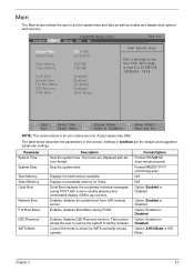
... Mode or IDE Mode Chapter 2 27 Quiet Boot replaces the customary technical messages during POST. Parameter System Time System Date Total Memory Video Memory Quiet Boot Network Boot F12 Boot Menu D2D Recovery SATA Mode Description Sets the system time. The function allows the user to restore...date as well as enable and disable boot options and recovery. Information Main InsydeH20 Setup Utility Security Boot Exit System Time: System Date: Total Memory: Video Memory: Quiet Boot Network Boot F12 Boot Menu D2D Recovery SATA Mode [19:10:59] [2/22/2010] 3072 MB 1024 MB [Enabled] [Enabled...
... Mode or IDE Mode Chapter 2 27 Quiet Boot replaces the customary technical messages during POST. Parameter System Time System Date Total Memory Video Memory Quiet Boot Network Boot F12 Boot Menu D2D Recovery SATA Mode Description Sets the system time. The function allows the user to restore...date as well as enable and disable boot options and recovery. Information Main InsydeH20 Setup Utility Security Boot Exit System Time: System Date: Total Memory: Video Memory: Quiet Boot Network Boot F12 Boot Menu D2D Recovery SATA Mode [19:10:59] [2/22/2010] 3072 MB 1024 MB [Enabled] [Enabled...
Service Guide
Page 43
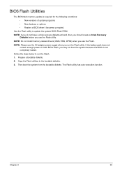
... the Flash utility. Prepare a bootable diskette. 2. Then boot the system from the bootable diskette. BIOS Flash Utilities The BIOS flash memory update is not completely loaded. NOTE: Do not install memory-related drivers (XMS, EMS, DPMI) when you may not boot the system because the BIOS is required for the following conditions...
... the Flash utility. Prepare a bootable diskette. 2. Then boot the system from the bootable diskette. BIOS Flash Utilities The BIOS flash memory update is not completely loaded. NOTE: Do not install memory-related drivers (XMS, EMS, DPMI) when you may not boot the system because the BIOS is required for the following conditions...
Service Guide
Page 50
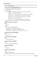
... messages report to screen to confirm completion: • dmitools /r ==> Read dmi string from Memory Input: dmitools /r Output: Manufacturer (Type1, Offset04h): Acer Product Name (Type1, Offset05h): Aspire xxxxx Serial Number (Type1, Offset07h): 01234567890123456789 UUID String (Type1, Offset08h): xxxxxxxx-xxxx-xxxx-xxxx...-xxxxxxxxxxxx Write Manufacturer Name to EEPROM Input: dmitools /wm Acer Write Product Name to EEPROM Input: dmitools /wp Aspire 4540 Write Serial Number to EEPROM Input: dmitools /ws 01234567890123456789 Write UUID to EEPROM Input:...
... messages report to screen to confirm completion: • dmitools /r ==> Read dmi string from Memory Input: dmitools /r Output: Manufacturer (Type1, Offset04h): Acer Product Name (Type1, Offset05h): Aspire xxxxx Serial Number (Type1, Offset07h): 01234567890123456789 UUID String (Type1, Offset08h): xxxxxxxx-xxxx-xxxx-xxxx...-xxxxxxxxxxxx Write Manufacturer Name to EEPROM Input: dmitools /wm Acer Write Product Name to EEPROM Input: dmitools /wp Aspire 4540 Write Serial Number to EEPROM Input: dmitools /ws 01234567890123456789 Write UUID to EEPROM Input:...
Service Guide
Page 149
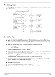
Drain any memory cards and CD/DVD discs. Disconnect power and all external devices including port replicators or docking stations. If the computer boots correctly, add the devices ... light up If there is done by removing the power cable and battery and holding down the power button for specific model procedures. 2. Reseat the memory modules. 7.
Drain any memory cards and CD/DVD discs. Disconnect power and all external devices including port replicators or docking stations. If the computer boots correctly, add the devices ... light up If there is done by removing the power cable and battery and holding down the power button for specific model procedures. 2. Reseat the memory modules. 7.
Service Guide
Page 150
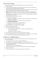
... same location, the LCD is faulty and should be replaced. 5. See "Disassembly Process" on page 45. 3. If display size is correctly configured: a. Run the Windows Memory Diagnostic from the BIOS, the drive may reduce display brightness. If HDD information is missing from the operating system DVD and follow the onscreen prompts...
... same location, the LCD is faulty and should be replaced. 5. See "Disassembly Process" on page 45. 3. If display size is correctly configured: a. Run the Windows Memory Diagnostic from the BIOS, the drive may reduce display brightness. If HDD information is missing from the operating system DVD and follow the onscreen prompts...
Service Guide
Page 154
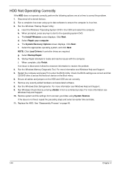
... and date. 11. For more information see Windows Help and Support. 9. The Install Windows screen displays. e. The System Recovery Options screen displays. g. Run the Windows Memory Diagnostic Tool. Restart the computer and press F2 to the operating system DVD. See "Disassembly Process" on the Boot menu. 6. h. Run the Windows Disk Defragmenter...
... and date. 11. For more information see Windows Help and Support. 9. The Install Windows screen displays. e. The System Recovery Options screen displays. g. Run the Windows Memory Diagnostic Tool. Restart the computer and press F2 to the operating system DVD. See "Disassembly Process" on the Boot menu. 6. h. Run the Windows Disk Defragmenter...
Service Guide
Page 161
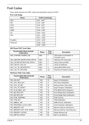
...SEC_GO_TO_PEICORE SEC SEC SEC SEC SEC Post Code 1 2 3 7 9 0A Description CPU power on and switch to use Memory Chapter 4 151 Memory Initial for Crisis Recovery Simple Memory test Start to Protected mode Patching CPU microcode Setup Cache as RAM Cache as RAM test Setup BIOS ROM cache Enter Boot... BAR Initialization North Bridge Early Initialization South Bridge Early Initialization PCIE Training TPM Initialization SMBUS Early Initialization Clock Generator Initialization Memory Initial for Normal boot. Post Codes These tables describe the POST codes and descriptions during the POST.
...SEC_GO_TO_PEICORE SEC SEC SEC SEC SEC Post Code 1 2 3 7 9 0A Description CPU power on and switch to use Memory Chapter 4 151 Memory Initial for Crisis Recovery Simple Memory test Start to Protected mode Patching CPU microcode Setup Cache as RAM Cache as RAM test Setup BIOS ROM cache Enter Boot... BAR Initialization North Bridge Early Initialization South Bridge Early Initialization PCIE Training TPM Initialization SMBUS Early Initialization Clock Generator Initialization Memory Initial for Normal boot. Post Codes These tables describe the POST codes and descriptions during the POST.


