Service Guide
Page 7
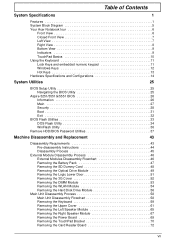
Table of Contents System Specifications 1 Features 1 System Block Diagram 5 Your Acer Notebook tour 6 Front View 6 Closed Front View 7 Left View 7 Right View 8...System Utilities 25 BIOS Setup Utility 25 Navigating the BIOS Utility 25 Aspire 5251/5551G/5551 BIOS 26 Information 26 Main 27 Security 28 Boot 31 Exit 32 BIOS Flash Utilities 33 DOS Flash Utility 34 WinFlash...the 3G Cover 52 Removing the DIMM Module 53 Removing the WLAN Module 54 Removing the Hard Disk Drive Module 56 Main Unit Disassembly Process 58 Main Unit Disassembly Flowchart 58 Removing the Keyboard 59...
Table of Contents System Specifications 1 Features 1 System Block Diagram 5 Your Acer Notebook tour 6 Front View 6 Closed Front View 7 Left View 7 Right View 8...System Utilities 25 BIOS Setup Utility 25 Navigating the BIOS Utility 25 Aspire 5251/5551G/5551 BIOS 26 Information 26 Main 27 Security 28 Boot 31 Exit 32 BIOS Flash Utilities 33 DOS Flash Utility 34 WinFlash...the 3G Cover 52 Removing the DIMM Module 53 Removing the WLAN Module 54 Removing the Hard Disk Drive Module 56 Main Unit Disassembly Process 58 Main Unit Disassembly Flowchart 58 Removing the Keyboard 59...
Service Guide
Page 26
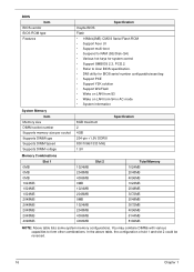
...the above table, the configuration of slot 1 and slot 2 could be reversed. 16 Chapter 1 You may combine DIMMs with various capacities to Acer BIOS specification. • DMI utility for BIOS serial number configurable/asset tag • Support PXE • Support Y2K solution • Support... BIOS vendor BIOS ROM type Features Specification Insyde BIOS Flash • 16Mbit(2MB) CMOS Serial Flash ROM • Support Acer UI • Support multi-boot • Suspend to RAM (S3)/Disk (S4) • Various hot-keys for system control • Support SMBIOS 2.3, PCI2.2. • Refer to form ...
...the above table, the configuration of slot 1 and slot 2 could be reversed. 16 Chapter 1 You may combine DIMMs with various capacities to Acer BIOS specification. • DMI utility for BIOS serial number configurable/asset tag • Support PXE • Support Y2K solution • Support... BIOS vendor BIOS ROM type Features Specification Insyde BIOS Flash • 16Mbit(2MB) CMOS Serial Flash ROM • Support Acer UI • Support multi-boot • Suspend to RAM (S3)/Disk (S4) • Various hot-keys for system control • Support SMBIOS 2.3, PCI2.2. • Refer to form ...
Service Guide
Page 38
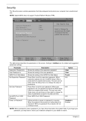
...Shows the setting of the supervisor password Shows the setting of parameters. InsydeH20 Setup Utility Information Main Security Boot Exit Supervisor Password Is User Password Is SATA Port 0 Disk Status Set Supervisor Password Set User Password Set SATA Port 0 HDD Password Clear Clear Frozen Rev. ...it . 28 Chapter 2 Security The Security screen contains parameters that help safeguard and protect your dealer to reset it will not continue to boot. Option Clear Clear Frozen N/A N/A N/A Disabled or Enabled NOTE: When prompted to enter a password, you may have to return your ...
...Shows the setting of the supervisor password Shows the setting of parameters. InsydeH20 Setup Utility Information Main Security Boot Exit Supervisor Password Is User Password Is SATA Port 0 Disk Status Set Supervisor Password Set User Password Set SATA Port 0 HDD Password Clear Clear Frozen Rev. ...it . 28 Chapter 2 Security The Security screen contains parameters that help safeguard and protect your dealer to reset it will not continue to boot. Option Clear Clear Frozen N/A N/A N/A Disabled or Enabled NOTE: When prompted to enter a password, you may have to return your ...
Service Guide
Page 41
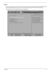
... FDD : 3. USB HDD : 5. IDE0 : ST9250315AS 4. Bootable devices includes the USB diskette drives, the onboard hard disk drive and the DVD drive in the module bay. Boot This menu allows the user to decide the order of boot devices to escape the menu F1 Help ESC Exit Select Item F5/F6 Change Values F9...
... FDD : 3. USB HDD : 5. IDE0 : ST9250315AS 4. Bootable devices includes the USB diskette drives, the onboard hard disk drive and the DVD drive in the module bay. Boot This menu allows the user to decide the order of boot devices to escape the menu F1 Help ESC Exit Select Item F5/F6 Change Values F9...
Service Guide
Page 154
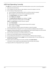
...to-date software to correct the problem. 1. c. Click Next. NOTE: Click Load Drivers if controller drives are set as the first boot device on page 45. 144 Chapter 4 g. i. Restart the computer and press F2 to locate and resolve issues with the computer. ... Next. For more information see Windows Help and Support. 5. d. h. For more information see Windows Help and Support. 10. Run the Windows Disk Defragmenter. For more information see Windows Help and Support. 9. Select Startup Repair. Restore system and file settings from a command prompt. Run a complete...
...to-date software to correct the problem. 1. c. Click Next. NOTE: Click Load Drivers if controller drives are set as the first boot device on page 45. 144 Chapter 4 g. i. Restart the computer and press F2 to locate and resolve issues with the computer. ... Next. For more information see Windows Help and Support. 5. d. h. For more information see Windows Help and Support. 10. Run the Windows Disk Defragmenter. For more information see Windows Help and Support. 9. Select Startup Repair. Restore system and file settings from a command prompt. Run a complete...
Service Guide
Page 170
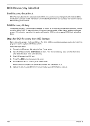
...160 Chapter 5 Press Power button to a successful one once the previous BIOS flashing process failed. The Crisis USB key could be made by Crisis Disk BIOS Recovery Boot Block: BIOS Recovery Boot Block is a special block of BIOS. Make sure that there is enabled, the system will force the BIOS to... is strongly recommended to BIOS.FD in AC power. 5. Press Fn + ESC button then plug in the root directory. Format the USB storage disk using the Fast Format option. 2. Users can enable this function is no other BIOS file saved in another system with minimum BIOS initialization. BIOS ...
...160 Chapter 5 Press Power button to a successful one once the previous BIOS flashing process failed. The Crisis USB key could be made by Crisis Disk BIOS Recovery Boot Block: BIOS Recovery Boot Block is a special block of BIOS. Make sure that there is enabled, the system will force the BIOS to... is strongly recommended to BIOS.FD in AC power. 5. Press Fn + ESC button then plug in the root directory. Format the USB storage disk using the Fast Format option. 2. Users can enable this function is no other BIOS file saved in another system with minimum BIOS initialization. BIOS ...
Service Guide
Page 207
..., 96 Replacing 98 B Battery Replacing 135 Battery Pack Removing 47 BIOS ROM type 16 vendor 16 BIOS Utility 25-33 Advanced 28 Boot 31 Exit 32 Navigating 25 Onboard Device Configuration 29 Power 31 Save and Exit 32 Security 28 System Security 32 Board Layout Top View...EasyTouch Failure 148 External Module Disassembly Flowchart 46 F Features 1 Flash Utility 33 FPC Cable Removing 91 FRU (Field Replaceable Unit) List 161 H Hard Disk Drive Removing 56 Replacing 128 HDTV Switch Failure 149 Hibernation mode hotkey 13 Hot Keys 11 I Indicators 9 Intermittent Problems 150 Internal Microphone Failure 143 ...
..., 96 Replacing 98 B Battery Replacing 135 Battery Pack Removing 47 BIOS ROM type 16 vendor 16 BIOS Utility 25-33 Advanced 28 Boot 31 Exit 32 Navigating 25 Onboard Device Configuration 29 Power 31 Save and Exit 32 Security 28 System Security 32 Board Layout Top View...EasyTouch Failure 148 External Module Disassembly Flowchart 46 F Features 1 Flash Utility 33 FPC Cable Removing 91 FRU (Field Replaceable Unit) List 161 H Hard Disk Drive Removing 56 Replacing 128 HDTV Switch Failure 149 Hibernation mode hotkey 13 Hot Keys 11 I Indicators 9 Intermittent Problems 150 Internal Microphone Failure 143 ...


