Service Guide
Page 5
... capability). Please note WHEN ORDERING FRU PARTS, that you with further technical details. 2. You MUST use the list provided by your Acer office may have decided to order FRU parts for repair and service of this information and the product it will NOT be noted in.... If, for Acer's "global" product offering. To better fit local market requirements and enhance product competitiveness, your regional offices or the responsible personnel/channel to provide you with all technical information relating to those given in the printed Service Guide. In such cases, please contact your...
... capability). Please note WHEN ORDERING FRU PARTS, that you with further technical details. 2. You MUST use the list provided by your Acer office may have decided to order FRU parts for repair and service of this information and the product it will NOT be noted in.... If, for Acer's "global" product offering. To better fit local market requirements and enhance product competitiveness, your regional offices or the responsible personnel/channel to provide you with all technical information relating to those given in the printed Service Guide. In such cases, please contact your...
Service Guide
Page 39
... setting the password, the computer sets the Supervisor Password parameter to "Clear". 4. Removing a Password Follow these steps as you can not exceed 8 alphanumeric characters (A-Z, a-z, 0-9, not case sensitive). The Set Password box appears: Set Supervisor Password Enter Current Password [ ] Enter New Password [ ] Confirm New Password [ ] 2. The computer then sets the Supervisor Password...
... setting the password, the computer sets the Supervisor Password parameter to "Clear". 4. Removing a Password Follow these steps as you can not exceed 8 alphanumeric characters (A-Z, a-z, 0-9, not case sensitive). The Set Password box appears: Set Supervisor Password Enter Current Password [ ] Enter New Password [ ] Confirm New Password [ ] 2. The computer then sets the Supervisor Password...
Service Guide
Page 74
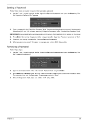
Step Upper Cover Size M2.5*5 Quantity 7 Screw Type 10. Starting at the top right side of the Lower Cover. 64 Chapter 3 Work along the front edge of the casing to the left as shown, then lift the Upper Cover clear of the cover, pry apart the Upper and Lower Covers as shown. Remove the seven (7) screws on the Upper Cover as shown. 9.
Step Upper Cover Size M2.5*5 Quantity 7 Screw Type 10. Starting at the top right side of the Lower Cover. 64 Chapter 3 Work along the front edge of the casing to the left as shown, then lift the Upper Cover clear of the cover, pry apart the Upper and Lower Covers as shown. Remove the seven (7) screws on the Upper Cover as shown. 9.
Service Guide
Page 88
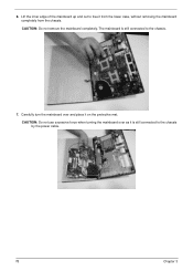
The mainboard is still connected to the chassis by the power cable. 78 Chapter 3 Lift the inner edge of the mainboard up and out to the chassis. 7. CAUTION: Do not remove the mainboard completely. Carefully turn the mainboard over as it is still connected to free it on the protective mat. CAUTION: Do not use excessive force when turning the mainboard over and place it from the lower case, without removing the mainboard completely from the chassis. 6.
The mainboard is still connected to the chassis by the power cable. 78 Chapter 3 Lift the inner edge of the mainboard up and out to the chassis. 7. CAUTION: Do not remove the mainboard completely. Carefully turn the mainboard over as it is still connected to free it on the protective mat. CAUTION: Do not use excessive force when turning the mainboard over and place it from the lower case, without removing the mainboard completely from the chassis. 6.
Service Guide
Page 123
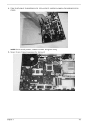
Place the left edge of the mainboard in first to line up the I /O ports are positioned correctly through the casing. 5. Secure the one (1) securing screw on the Mainboard. Chapter 3 113 4. NOTE: Ensure the I /O ports before lowering the mainboard into the chassis.
Place the left edge of the mainboard in first to line up the I /O ports are positioned correctly through the casing. 5. Secure the one (1) securing screw on the Mainboard. Chapter 3 113 4. NOTE: Ensure the I /O ports before lowering the mainboard into the chassis.
Service Guide
Page 143
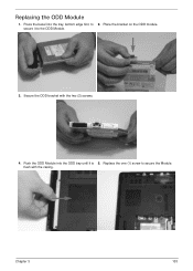
Secure the ODD bracket with the casing. Push the ODD Module into the tray, bottom edge first, to 2. Chapter 3 133 flush with the two (2) screws. 4. Replace the one (1) screw to the ODD Module. 3. secure it is 5. Place the bracket on the ODD module. Press the bezel into the ODD bay until it to secure the Module. Replacing the ODD Module 1.
Secure the ODD bracket with the casing. Push the ODD Module into the tray, bottom edge first, to 2. Chapter 3 133 flush with the two (2) screws. 4. Replace the one (1) screw to the ODD Module. 3. secure it is 5. Place the bracket on the ODD module. Press the bezel into the ODD bay until it to secure the Module. Replacing the ODD Module 1.
Service Guide
Page 144
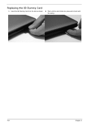
Insert the SD Dummy Card into place and is flush with the casing. 134 Chapter 3 Push until the card clicks into the slot as shown. 2. Replacing the SD Dummy Card 1.
Insert the SD Dummy Card into place and is flush with the casing. 134 Chapter 3 Push until the card clicks into the slot as shown. 2. Replacing the SD Dummy Card 1.
Service Guide
Page 148
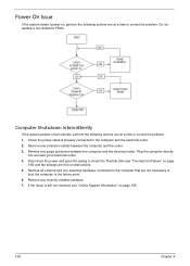
Remove any surge protectors between the computer and the outlet. 3. Disconnect the power and open the casing to check the Thermal Unit (see "Online Support Information" on page 195. 138 Chapter 4 If the Issue is properly connected to the computer and the ...
Remove any surge protectors between the computer and the outlet. 3. Disconnect the power and open the casing to check the Thermal Unit (see "Online Support Information" on page 195. 138 Chapter 4 If the Issue is properly connected to the computer and the ...


