Service Guide
Page 7
...Acer Notebook tour 6 Front View 6 Closed Front View 7 Left View 7 Right View 8 Bottom View 9 Indicators 9 TouchPad Basics 10 Using the Keyboard 11 Lock Keys and embedded numeric keypad 11 Windows Keys 12 Hot Keys 13 Hardware Specifications and Configurations 14 System Utilities 25 BIOS Setup Utility 25 Navigating the BIOS Utility 25 Aspire 5251.../5551G/5551 BIOS 26 Information 26 Main 27 Security 28 Boot 31 Exit 32 BIOS Flash Utilities 33 DOS Flash Utility 34 WinFlash Utility 36 Remove HDD/BIOS Password Utilities 37 ...
...Acer Notebook tour 6 Front View 6 Closed Front View 7 Left View 7 Right View 8 Bottom View 9 Indicators 9 TouchPad Basics 10 Using the Keyboard 11 Lock Keys and embedded numeric keypad 11 Windows Keys 12 Hot Keys 13 Hardware Specifications and Configurations 14 System Utilities 25 BIOS Setup Utility 25 Navigating the BIOS Utility 25 Aspire 5251.../5551G/5551 BIOS 26 Information 26 Main 27 Security 28 Boot 31 Exit 32 BIOS Flash Utilities 33 DOS Flash Utility 34 WinFlash Utility 36 Remove HDD/BIOS Password Utilities 37 ...
Service Guide
Page 8
... Disassembly Process 84 LCD Module Disassembly Flowchart 84 Removing the LCD Assembly 85 Removing the LCD Bezel 88 Removing the Camera Module 89 Removing the LCD Panel 90 Removing the LCD Brackets and LVDS Cable 91 Removing the Microphone Cable 94 Removing the Antennas 96 LCD Module Reassembly Procedure 98 ...Power Board 121 Replacing the Right Speaker Module 122 Replacing the Left Speaker Module 123 Replacing the Upper Cover 124 Replacing the Keyboard 127 Replacing the Hard Disk Drive Module 128 Replacing the WLAN Module 129 Replacing the DIMM Modules 130 Replacing the 3G Cover...
... Disassembly Process 84 LCD Module Disassembly Flowchart 84 Removing the LCD Assembly 85 Removing the LCD Bezel 88 Removing the Camera Module 89 Removing the LCD Panel 90 Removing the LCD Brackets and LVDS Cable 91 Removing the Microphone Cable 94 Removing the Antennas 96 LCD Module Reassembly Procedure 98 ...Power Board 121 Replacing the Right Speaker Module 122 Replacing the Left Speaker Module 123 Replacing the Upper Cover 124 Replacing the Keyboard 127 Replacing the Hard Disk Drive Module 128 Replacing the WLAN Module 129 Replacing the DIMM Modules 130 Replacing the 3G Cover...
Service Guide
Page 55
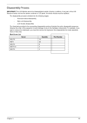
The disassembly process is faulty, such as the camera, antenna or LCD panel, the whole module must first remove the keyboard, then disassemble the inside assembly frame in the succeeding disassembly sections illustrate the entire disassembly sequence. For example, if you want to any part of ... Screw List Screw Quantity Part Number M2.5*8 19 M2*3 26 M2.5*5 8 M2.5*3.2 4 M2.5*6 4 Chapter 3 45 Observe the order of the sequence to avoid damage to remove the mainboard, you must be disassembled outside of the hardware components. If any of factory conditions.
The disassembly process is faulty, such as the camera, antenna or LCD panel, the whole module must first remove the keyboard, then disassemble the inside assembly frame in the succeeding disassembly sections illustrate the entire disassembly sequence. For example, if you want to any part of ... Screw List Screw Quantity Part Number M2.5*8 19 M2*3 26 M2.5*5 8 M2.5*3.2 4 M2.5*6 4 Chapter 3 45 Observe the order of the sequence to avoid damage to remove the mainboard, you must be disassembled outside of the hardware components. If any of factory conditions.
Service Guide
Page 56
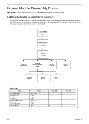
.... For example, if you want to remove the keyboard, you on the components that need to be removed during servicing. External Module Disassembly Process IMPORTANT: The outside housing and color may vary from system Remove Battery Remove Dummy Card Remove HDD/WLAN/DIM M Door Remove 3G Cover Remove ODD Remove DIMMs Remove WLAN Remove HDD Screw List Step ODD Module ODD... No. 46 Chapter 3 External Modules Disassembly Flowchart The flowchart below gives you a graphic representation of the external module disassembly sequence and instructs you must first remove the switch board.
.... For example, if you want to remove the keyboard, you on the components that need to be removed during servicing. External Module Disassembly Process IMPORTANT: The outside housing and color may vary from system Remove Battery Remove Dummy Card Remove HDD/WLAN/DIM M Door Remove 3G Cover Remove ODD Remove DIMMs Remove WLAN Remove HDD Screw List Step ODD Module ODD... No. 46 Chapter 3 External Modules Disassembly Flowchart The flowchart below gives you a graphic representation of the external module disassembly sequence and instructs you must first remove the switch board.
Service Guide
Page 68
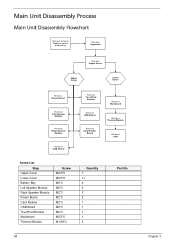
Main Unit Disassembly Process Main Unit Disassembly Flowchart Remove External Modules before proceeding Remove Keyboard Remove Upper Cover Upper Cover Lower Cover Remove Power Board Remove Left Speaker Module Remove Right Speaker Module Remove USB Board Remove TouchPad Bracket Remove USB Board Remove Card Reader Board Remove Mainboard Remove Thermal Module Remove CPU Screw List Step Upper Cover Lower Cover Battery Bay Left Speaker Module...
Main Unit Disassembly Process Main Unit Disassembly Flowchart Remove External Modules before proceeding Remove Keyboard Remove Upper Cover Upper Cover Lower Cover Remove Power Board Remove Left Speaker Module Remove Right Speaker Module Remove USB Board Remove TouchPad Bracket Remove USB Board Remove Card Reader Board Remove Mainboard Remove Thermal Module Remove CPU Screw List Step Upper Cover Lower Cover Battery Bay Left Speaker Module...
Service Guide
Page 69
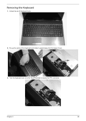
Pry up the centre of the Keyboard and rotate it upward away from the Upper Cover. 3. Chapter 3 59 Removing the Keyboard 1. Turn the keyboard over on to the TouchPad area to expose the FFC connector. Unlock the six (6) keyboard locks. 2.
Pry up the centre of the Keyboard and rotate it upward away from the Upper Cover. 3. Chapter 3 59 Removing the Keyboard 1. Turn the keyboard over on to the TouchPad area to expose the FFC connector. Unlock the six (6) keyboard locks. 2.
Service Guide
Page 207
...Security 28 System Security 32 Board Layout Top View 155 brightness hotkeys 13 C Camera Module Removing 89 Replacing 101, 103, 104, 106 Common Problems 138 computer on indicator 9 CPU Removing 83 Replacing 109 D DIMM Modules Replacing 130 Display 5 Index display hotkeys 13 E ...161 H Hard Disk Drive Removing 56 Replacing 128 HDTV Switch Failure 149 Hibernation mode hotkey 13 Hot Keys 11 I Indicators 9 Intermittent Problems 150 Internal Microphone Failure 143 Internal Speaker Failure 142 J Jumper and Connector Locations 155 K Keyboard Removing 59 Replacing 127 Keyboard Failure 141 L LCD Bezel...
...Security 28 System Security 32 Board Layout Top View 155 brightness hotkeys 13 C Camera Module Removing 89 Replacing 101, 103, 104, 106 Common Problems 138 computer on indicator 9 CPU Removing 83 Replacing 109 D DIMM Modules Replacing 130 Display 5 Index display hotkeys 13 E ...161 H Hard Disk Drive Removing 56 Replacing 128 HDTV Switch Failure 149 Hibernation mode hotkey 13 Hot Keys 11 I Indicators 9 Intermittent Problems 150 Internal Microphone Failure 143 Internal Speaker Failure 142 J Jumper and Connector Locations 155 K Keyboard Removing 59 Replacing 127 Keyboard Failure 141 L LCD Bezel...


