
Service Guide
Page 7
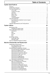
Table of Contents System Specifications 1 Features 1 System Block Diagram 5 Your Acer Notebook tour 6 Front View 6 Closed Front View 7 Left View 7 Right View 8 Bottom View 9 Indicators 9 TouchPad Basics 10 Using the Keyboard 11 Lock Keys and embedded ... Hot Keys 13 Hardware Specifications and Configurations 14 System Utilities 25 BIOS Setup Utility 25 Navigating the BIOS Utility 25 Aspire 5251/5551G/5551 BIOS 26 Information 26 Main 27 Security 28 Boot 31 Exit 32 BIOS Flash Utilities 33 DOS Flash Utility 34 WinFlash Utility 36 Remove HDD/BIOS Password Utilities 37...
Table of Contents System Specifications 1 Features 1 System Block Diagram 5 Your Acer Notebook tour 6 Front View 6 Closed Front View 7 Left View 7 Right View 8 Bottom View 9 Indicators 9 TouchPad Basics 10 Using the Keyboard 11 Lock Keys and embedded ... Hot Keys 13 Hardware Specifications and Configurations 14 System Utilities 25 BIOS Setup Utility 25 Navigating the BIOS Utility 25 Aspire 5251/5551G/5551 BIOS 26 Information 26 Main 27 Security 28 Boot 31 Exit 32 BIOS Flash Utilities 33 DOS Flash Utility 34 WinFlash Utility 36 Remove HDD/BIOS Password Utilities 37...
Service Guide
Page 26
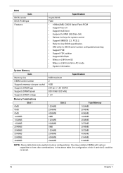
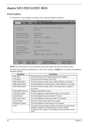
BIOS Item BIOS vendor BIOS ROM type Features Specification Insyde BIOS Flash • 16Mbit(2MB) CMOS Serial Flash ROM • Support Acer UI • Support multi-boot • Suspend to RAM (S3)/Disk (S4) • Various hot-keys for BIOS serial number configurable/asset tag •... 2048MB 3072MB 2048MB 3072MB 4096MB 6144MB 8192MB NOTE: Above table lists some system memory configurations. You may combine DIMMs with various capacities to Acer BIOS specification. • DMI utility for system control • Support SMBIOS 2.3, PCI2.2. • Refer to form other combinations. In...
BIOS Item BIOS vendor BIOS ROM type Features Specification Insyde BIOS Flash • 16Mbit(2MB) CMOS Serial Flash ROM • Support Acer UI • Support multi-boot • Suspend to RAM (S3)/Disk (S4) • Various hot-keys for BIOS serial number configurable/asset tag •... 2048MB 3072MB 2048MB 3072MB 4096MB 6144MB 8192MB NOTE: Above table lists some system memory configurations. You may combine DIMMs with various capacities to Acer BIOS specification. • DMI utility for system control • Support SMBIOS 2.3, PCI2.2. • Refer to form other combinations. In...
Service Guide
Page 27
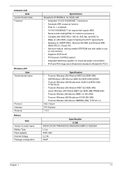
... (WOL) support meeting the ACPI requirements • Statistics for SNMP MIB II, Ethernet-like MIB, and Ethernet MIB (IEEE 802.3z, Clause 30) • Self-boot feature, utilizing smaller EEPROM size with ability to use on-chip memory • Supports iSCSI boott • PCI Express CLKREQ support • Integrated switching regulator...
... (WOL) support meeting the ACPI requirements • Statistics for SNMP MIB II, Ethernet-like MIB, and Ethernet MIB (IEEE 802.3z, Clause 30) • Self-boot feature, utilizing smaller EEPROM size with ability to use on-chip memory • Supports iSCSI boott • PCI Express CLKREQ support • Integrated switching regulator...
Service Guide
Page 35
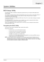
... a menu, use the left and right arrow keys. • To choose an item, use the up and down arrow keys. • To change boot device without entering BIOS SETUP Utility. You can load default settings by pressing F9. Help for a particular menu are shown on the bottom of F12... Setup" message is set the parameter to "disabled". NOTE: You can change the value of the screen. In this menu, user can change boot device without entering BIOS Setup Utility, please set to "enabled". Please note that system information is enclosed in square brackets. Navigating the BIOS Utility ...
... a menu, use the left and right arrow keys. • To choose an item, use the up and down arrow keys. • To change boot device without entering BIOS SETUP Utility. You can load default settings by pressing F9. Help for a particular menu are shown on the bottom of F12... Setup" message is set the parameter to "disabled". NOTE: You can change the value of the screen. In this menu, user can change boot device without entering BIOS Setup Utility, please set to "enabled". Please note that system information is enclosed in square brackets. Navigating the BIOS Utility ...
Service Guide
Page 36
...this screen. Actual values may differ according to model. This field shows the model name of the system. InsydeH20 Setup Utility Information Main Security Boot Exit Rev. 3.5 CPU Type CPU Speed HDD Model Name: HDD Serial Number: ATAPI Model Name: System BIOS Version: VGA BIOS Version: Serial... Dual-Core Processor 2500 MHz ST9250315AS 5VC8CXKX Slimtype DVD A DS8A2SH V0. 17T01 ATI VER0.12. 017. 000. 000. 034815 123456789 Aspire 5251/5551G/5551 Acer AE088D61-0B71-782C-94D7-705AB6401288 F1 Help ESC Exit Select Item F5/F6 Change Values F9 Setup Default Select Menu Enter Select SubMenu F10...
...this screen. Actual values may differ according to model. This field shows the model name of the system. InsydeH20 Setup Utility Information Main Security Boot Exit Rev. 3.5 CPU Type CPU Speed HDD Model Name: HDD Serial Number: ATAPI Model Name: System BIOS Version: VGA BIOS Version: Serial... Dual-Core Processor 2500 MHz ST9250315AS 5VC8CXKX Slimtype DVD A DS8A2SH V0. 17T01 ATI VER0.12. 017. 000. 000. 034815 123456789 Aspire 5251/5551G/5551 Acer AE088D61-0B71-782C-94D7-705AB6401288 F1 Help ESC Exit Select Item F5/F6 Change Values F9 Setup Default Select Menu Enter Select SubMenu F10...
Service Guide
Page 37
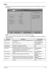
... POST with 24hour format. Valid range is from LAN (remote server). Control the mode in this screen. Enables, disables the system boot from 0 to 23.REDUCE /INCREASE : F5/F6 F1 Help ESC Exit Select Item F5/F6 Change Values F9 Setup Default Select ...Disabled Option: Enabled or Disabled Option: AHCI Mode or IDE Mode Chapter 2 27 Information Main InsydeH20 Setup Utility Security Boot Exit System Time: System Date: Total Memory: Video Memory: Quiet Boot Network Boot F12 Boot Menu D2D Recovery SATA Mode [19:10:59] [2/22/2010] 3072 MB 1024 MB [Enabled] [Enabled] [...
... POST with 24hour format. Valid range is from LAN (remote server). Control the mode in this screen. Enables, disables the system boot from 0 to 23.REDUCE /INCREASE : F5/F6 F1 Help ESC Exit Select Item F5/F6 Change Values F9 Setup Default Select ...Disabled Option: Enabled or Disabled Option: AHCI Mode or IDE Mode Chapter 2 27 Information Main InsydeH20 Setup Utility Security Boot Exit System Time: System Date: Total Memory: Video Memory: Quiet Boot Network Boot F12 Boot Menu D2D Recovery SATA Mode [19:10:59] [2/22/2010] 3072 MB 1024 MB [Enabled] [Enabled] [...
Service Guide
Page 38
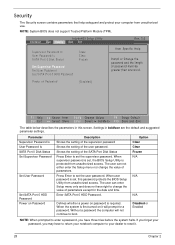
.... The user can not either enter the Setup menu nor change the value of the SATA Port Disk Status Press Enter to boot. InsydeH20 Setup Utility Information Main Security Boot Exit Supervisor Password Is User Password Is SATA Port 0 Disk Status Set Supervisor Password Set User Password Set SATA Port 0 HDD Password...
.... The user can not either enter the Setup menu nor change the value of the SATA Port Disk Status Press Enter to boot. InsydeH20 Setup Utility Information Main Security Boot Exit Supervisor Password Is User Password Is SATA Port 0 Disk Status Set Supervisor Password Set User Password Set SATA Port 0 HDD Password...
Service Guide
Page 41
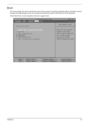
...list. USB FDD : 3. IDE1 : Slimtype DVD A DS8A4SH Use < > or < > to select a device, then press to move it down the list, or to support boot. Bootable devices includes the USB diskette drives, the onboard hard disk drive and the DVD drive in the module bay. IDE0 : ST9250315AS 4. Press to load... the operating system. Network Boot : LEGACY PCI DEVICE 2. Boot This menu allows the user to decide the order of boot devices to escape the menu F1 Help ESC Exit Select Item F5/F6 Change Values F9 Setup Default ...
...list. USB FDD : 3. IDE1 : Slimtype DVD A DS8A4SH Use < > or < > to select a device, then press to move it down the list, or to support boot. Bootable devices includes the USB diskette drives, the onboard hard disk drive and the DVD drive in the module bay. IDE0 : ST9250315AS 4. Press to load... the operating system. Network Boot : LEGACY PCI DEVICE 2. Boot This menu allows the user to decide the order of boot devices to escape the menu F1 Help ESC Exit Select Item F5/F6 Change Values F9 Setup Default ...

Service Guide
Page 42
.... Load default values for all Setup items. Load previous values for all Setup items. Save setup data. 32 Chapter 2 Information Main InsydeH20 Setup Utility Security Boot Exit Rev. 3.5 Exit Saving Changes Exit Discarding Changes Load Setup Defaults Discard Changes Save Changes Item Specific Help Exit System Setup and save or discard...
.... Load default values for all Setup items. Load previous values for all Setup items. Save setup data. 32 Chapter 2 Information Main InsydeH20 Setup Utility Security Boot Exit Rev. 3.5 Exit Saving Changes Exit Discarding Changes Load Setup Defaults Discard Changes Save Changes Item Specific Help Exit System Setup and save or discard...
Service Guide
Page 43
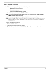
...steps below to finish BIOS Flash, you use the Flash. NOTE: Do not install memory-related drivers (XMS, EMS, DPMI) when you may not boot the system because the BIOS is required for the following conditions: • New versions of system programs • New features or options • ...Restore a BIOS when it becomes corrupted. Then boot the system from the bootable diskette. Use the Flash utility to the bootable diskette. 3. BIOS Flash Utilities The BIOS flash memory update is not ...
...steps below to finish BIOS Flash, you use the Flash. NOTE: Do not install memory-related drivers (XMS, EMS, DPMI) when you may not boot the system because the BIOS is required for the following conditions: • New versions of system programs • New features or options • ...Restore a BIOS when it becomes corrupted. Then boot the system from the bootable diskette. Use the Flash utility to the bootable diskette. 3. BIOS Flash Utilities The BIOS flash memory update is not ...
Service Guide
Page 44
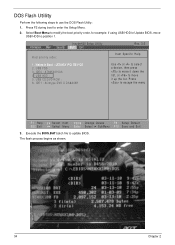
Press F2 during boot to position 1. Select Boot Menu to modify the boot priority order, for example, if using USB HDD to Update BIOS, move USB HDD to enter the Setup Menu. 2. USB HDD : 5. USB CD/DVD ROM : 6. ..., or to update BIOS. Execute the BIOS.BAT batch file to move it up the list. Network Boot : LEGACY PCI DEVICE 2. Press to use the DOS Flash Utility: 1. InsydeH20 Setup Utility Information Main Security Boot Exit Boot priority order: Rev. 3.5 Item Specific Help 1. IDE0 : ST9250315AS 4. DOS Flash Utility Perform the following steps to...
Press F2 during boot to position 1. Select Boot Menu to modify the boot priority order, for example, if using USB HDD to Update BIOS, move USB HDD to enter the Setup Menu. 2. USB HDD : 5. USB CD/DVD ROM : 6. ..., or to update BIOS. Execute the BIOS.BAT batch file to move it up the list. Network Boot : LEGACY PCI DEVICE 2. Press to use the DOS Flash Utility: 1. InsydeH20 Setup Utility Information Main Security Boot Exit Boot priority order: Rev. 3.5 Item Specific Help 1. IDE0 : ST9250315AS 4. DOS Flash Utility Perform the following steps to...
Service Guide
Page 49
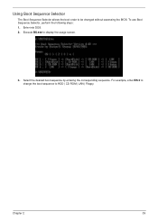
Enter into DOS. 2. Select the desired boot sequence by entering the corresponding sequence. To use Boot Sequence Selector, perform the following steps: 1. Execute BS.exe to be changed without accessing the BIOS. Using Boot Sequence Selector The Boot Sequence Selector allows the boot order to display the usage screen. 3. Chapter 2 39 For example, enter BS 2 to change the boot sequence to HDD | CD ROM | LAN | Floppy.
Enter into DOS. 2. Select the desired boot sequence by entering the corresponding sequence. To use Boot Sequence Selector, perform the following steps: 1. Execute BS.exe to be changed without accessing the BIOS. Using Boot Sequence Selector The Boot Sequence Selector allows the boot order to display the usage screen. 3. Chapter 2 39 For example, enter BS 2 to change the boot sequence to HDD | CD ROM | LAN | Floppy.
Service Guide
Page 50
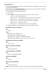
Boot into DOS. 2. To update the DMI Pool, perform the following examples show the commands and the corresponding output information. Execute dmitools. When the BIOS displays...management. The following messages report to screen to confirm completion: • dmitools /r ==> Read dmi string from Memory Input: dmitools /r Output: Manufacturer (Type1, Offset04h): Acer Product Name (Type1, Offset05h): Aspire xxxxx Serial Number (Type1, Offset07h): 01234567890123456789 UUID String (Type1, Offset08h): xxxxxxxx-xxxx-xxxx-xxxx-xxxxxxxxxxxx Write Manufacturer Name to EEPROM Input: dmitools /wm...
Boot into DOS. 2. To update the DMI Pool, perform the following examples show the commands and the corresponding output information. Execute dmitools. When the BIOS displays...management. The following messages report to screen to confirm completion: • dmitools /r ==> Read dmi string from Memory Input: dmitools /r Output: Manufacturer (Type1, Offset04h): Acer Product Name (Type1, Offset05h): Aspire xxxxx Serial Number (Type1, Offset07h): 01234567890123456789 UUID String (Type1, Offset08h): xxxxxxxx-xxxx-xxxx-xxxx-xxxxxxxxxxxx Write Manufacturer Name to EEPROM Input: dmitools /wm...
Service Guide
Page 148
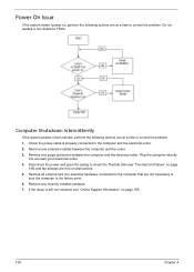
... correct the problem. 1. Check the power cable is still not resolved, see "Thermal Unit Failure" on page 148) and fan airways are not necessary to boot the computer to correct the problem. Remove any surge protectors between the computer and the outlet. 3. Remove any extension cables between the computer and the...
... correct the problem. 1. Check the power cable is still not resolved, see "Thermal Unit Failure" on page 148) and fan airways are not necessary to boot the computer to correct the problem. Remove any surge protectors between the computer and the outlet. 3. Remove any extension cables between the computer and the...
Service Guide
Page 149
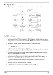
... removing the power cable and battery and holding down the power button for specific model procedures. 2. Reseat the memory modules. 7. Chapter 4 139 If the computer boots correctly, add the devices one by pressing Fn+F5. Make sure the computer has power by pressing Fn+F5 (on page 138. 3. If the POST...
... removing the power cable and battery and holding down the power button for specific model procedures. 2. Reseat the memory modules. 7. Chapter 4 139 If the computer boots correctly, add the devices one by pressing Fn+F5. Make sure the computer has power by pressing Fn+F5 (on page 138. 3. If the POST...

Service Guide
Page 154
... Restore. When prompted, press any recently added hardware and associated software. 8. d. f. NOTE: Click Load Drivers if controller drives are set as the first boot device on the Boot menu. 6. Select Startup Repair. If an issue is virus free. 3. Restart the computer and press F2 to locate and resolve issues with the computer...
... Restore. When prompted, press any recently added hardware and associated software. 8. d. f. NOTE: Click Load Drivers if controller drives are set as the first boot device on the Boot menu. 6. Select Startup Repair. If an issue is virus free. 3. Restart the computer and press F2 to locate and resolve issues with the computer...
Service Guide
Page 161
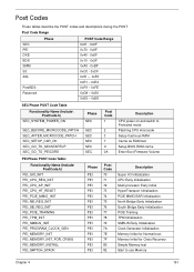
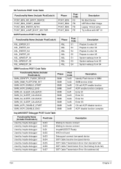
Memory Initial for Normal boot. Post Codes These tables describe the POST codes and descriptions during the POST. Post Code Range SEC PEI DXE BDS SMM S3 ASL Phase... Description CPU power on and switch to Protected mode Patching CPU microcode Setup Cache as RAM Cache as RAM test Setup BIOS ROM cache Enter Boot Firmware Volume PEI Phase POST Code Table: Functionality Name (Include\ PostCode.h) PEI_SIO_INIT PEI_CPU_REG_INIT PEI_CPU_AP_INIT PEI_CPU_HT_RESET PEI_PCIE_MMIO_INIT PEI_NB_REG_INIT PEI_SB_REG_INIT PEI_PCIE_TRAINING PEI_TPM_INIT PEI_SMBUS_INIT PEI_PROGRAM_CLOCK_GEN PEI_MEMORY_INIT ...
Memory Initial for Normal boot. Post Codes These tables describe the POST codes and descriptions during the POST. Post Code Range SEC PEI DXE BDS SMM S3 ASL Phase... Description CPU power on and switch to Protected mode Patching CPU microcode Setup Cache as RAM Cache as RAM test Setup BIOS ROM cache Enter Boot Firmware Volume PEI Phase POST Code Table: Functionality Name (Include\ PostCode.h) PEI_SIO_INIT PEI_CPU_REG_INIT PEI_CPU_AP_INIT PEI_CPU_HT_RESET PEI_PCIE_MMIO_INIT PEI_NB_REG_INIT PEI_SB_REG_INIT PEI_PCIE_TRAINING PEI_TPM_INIT PEI_SMBUS_INIT PEI_PROGRAM_CLOCK_GEN PEI_MEMORY_INIT ...
Service Guide
Page 163
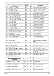
... BUS driver initialization Floppy device initialization Serial device initialization IDE device initialization AHCI device initialization Dispatch option ROMs Get boot device information End of boot selection Enter Setup Menu Enter Boot manager Try to boot system to OS Shadow Misc Option ROM 2D Save S3 resume required data in RAM 2E Last Chipset initial...
... BUS driver initialization Floppy device initialization Serial device initialization IDE device initialization AHCI device initialization Dispatch option ROMs Get boot device information End of boot selection Enter Setup Menu Enter Boot manager Try to boot system to OS Shadow Misc Option ROM 2D Save S3 resume required data in RAM 2E Last Chipset initial...
Service Guide
Page 164
... Functionality Name (Include\ PostCode.h) POST_BDS_NO_BOOT_DEVICE POST_BDS_START_IMAGE POST_BDS_ENTER_INT19 POST_BDS_JUMP_BOOT_SECTOR Phase POST_BDS POST_BDS POST_BDS POST_BDS Post Code F9 FB FD FE Description No Boot Device UEFI Boot Start Image Legacy 16 boot entry Try to Boot with INT 19 ACPI Functions POST Code Table Functionality Name (Include\ PostCode.h) ASL_ENTER_S1 ASL_ENTER_S3 ASL_ENTER_S4 ASL_ENTER_S5 ASL_WAKEUP_S1 ASL_WAKEUP_S3 ASL_WAKEUP_S4 Phase...
... Functionality Name (Include\ PostCode.h) POST_BDS_NO_BOOT_DEVICE POST_BDS_START_IMAGE POST_BDS_ENTER_INT19 POST_BDS_JUMP_BOOT_SECTOR Phase POST_BDS POST_BDS POST_BDS POST_BDS Post Code F9 FB FD FE Description No Boot Device UEFI Boot Start Image Legacy 16 boot entry Try to Boot with INT 19 ACPI Functions POST Code Table Functionality Name (Include\ PostCode.h) ASL_ENTER_S1 ASL_ENTER_S3 ASL_ENTER_S4 ASL_ENTER_S5 ASL_WAKEUP_S1 ASL_WAKEUP_S3 ASL_WAKEUP_S4 Phase...
Service Guide
Page 170
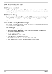
... ESC button then plug in another system with a workable BIOS. 6. Save ROM file (file name: NEW75x64.fd) to enter a special BIOS block, called Boot Block. Make sure that there is strongly recommended to initiate system CRISIS mode. Press Power button to have the AC adapter and Battery present. When...this function is a special block of BIOS. Plug USB storage into USB port. 4. If this machine by Crisis Disk BIOS Recovery Boot Block: BIOS Recovery Boot Block is enabled, the system will force the BIOS to BIOS.FD in the same directory. 3. Format the USB storage disk ...
... ESC button then plug in another system with a workable BIOS. 6. Save ROM file (file name: NEW75x64.fd) to enter a special BIOS block, called Boot Block. Make sure that there is strongly recommended to initiate system CRISIS mode. Press Power button to have the AC adapter and Battery present. When...this function is a special block of BIOS. Plug USB storage into USB port. 4. If this machine by Crisis Disk BIOS Recovery Boot Block: BIOS Recovery Boot Block is enabled, the system will force the BIOS to BIOS.FD in the same directory. 3. Format the USB storage disk ...


