Quick Start Guide
Page 5
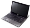
...Adobe Reader, access the Help and Support menu. It is not installed on your computer, clicking on your mobile computing needs. It covers basic topics such as system utilities, data recovery, expansion options and troubleshooting. This guide contains detailed information on AcerSystem User Guide. ...contained in certain models of the series, but not necessarily in the model you to use your Acer notebook, we have designed a set of your computer. The Aspire Series Generic User Guide contains useful information applying to thank you get started with language such as the...
...Adobe Reader, access the Help and Support menu. It is not installed on your computer, clicking on your mobile computing needs. It covers basic topics such as system utilities, data recovery, expansion options and troubleshooting. This guide contains detailed information on AcerSystem User Guide. ...contained in certain models of the series, but not necessarily in the model you to use your Acer notebook, we have designed a set of your computer. The Aspire Series Generic User Guide contains useful information applying to thank you get started with language such as the...
Quick Start Guide
Page 7
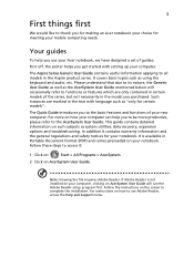
... Left and right speakers deliver stereo audio output. 11 Microphone Internal microphone for recording sound. 1. The front panel indicators are visible even when the computer cover is closed up.
... Left and right speakers deliver stereo audio output. 11 Microphone Internal microphone for recording sound. 1. The front panel indicators are visible even when the computer cover is closed up.
Quick Start Guide
Page 11
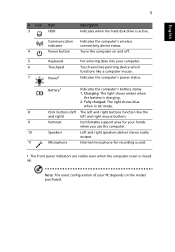
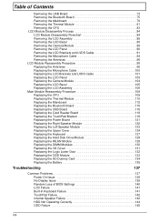
... disk bay Memory compartment Battery lock Description Houses the computer's battery pack. Releases the battery for removal. Locks the battery in position. Note: Do not cover or obstruct the opening of the fan. Houses the computer's hard disk (secured with screws). Environment • Temperature: • Operating: 5 °C to 35 °C •...
... disk bay Memory compartment Battery lock Description Houses the computer's battery pack. Releases the battery for removal. Locks the battery in position. Note: Do not cover or obstruct the opening of the fan. Houses the computer's hard disk (secured with screws). Environment • Temperature: • Operating: 5 °C to 35 °C •...
Service Guide
Page 5
...office MAY have a DIFFERENT part number code to order FRU parts for Acer's "global" product offering. These LOCALIZED FEATURES will not be covered in this printed Service Guide. add-on your regional Acer office to those given in the printed Service Guide. To better fit ...local market requirements and enhance product competitiveness, your Acer office may have decided to extend the functionality...
...office MAY have a DIFFERENT part number code to order FRU parts for Acer's "global" product offering. These LOCALIZED FEATURES will not be covered in this printed Service Guide. add-on your regional Acer office to those given in the printed Service Guide. To better fit ...local market requirements and enhance product competitiveness, your Acer office may have decided to extend the functionality...
Service Guide
Page 7
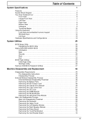
Table of Contents System Specifications 1 Features 1 System Block Diagram 5 Your Acer Notebook tour 6 Front View 6 Closed Front View 7 Left View 7 Right View... Specifications and Configurations 14 System Utilities 25 BIOS Setup Utility 25 Navigating the BIOS Utility 25 Aspire 5251/5551G/5551 BIOS 26 Information 26 Main 27 Security 28 Boot 31 Exit 32 BIOS Flash ... Unit Disassembly Process 58 Main Unit Disassembly Flowchart 58 Removing the Keyboard 59 Removing the Upper Cover 61 Removing the Left Speaker Module 65 Removing the Right Speaker Module 67 Removing the Power ...
Table of Contents System Specifications 1 Features 1 System Block Diagram 5 Your Acer Notebook tour 6 Front View 6 Closed Front View 7 Left View 7 Right View... Specifications and Configurations 14 System Utilities 25 BIOS Setup Utility 25 Navigating the BIOS Utility 25 Aspire 5251/5551G/5551 BIOS 26 Information 26 Main 27 Security 28 Boot 31 Exit 32 BIOS Flash ... Unit Disassembly Process 58 Main Unit Disassembly Flowchart 58 Removing the Keyboard 59 Removing the Upper Cover 61 Removing the Left Speaker Module 65 Removing the Right Speaker Module 67 Removing the Power ...
Service Guide
Page 8
... TouchPad Bracket 119 Replacing the Power Board 121 Replacing the Right Speaker Module 122 Replacing the Left Speaker Module 123 Replacing the Upper Cover 124 Replacing the Keyboard 127 Replacing the Hard Disk Drive Module 128 Replacing the WLAN Module 129 Replacing the DIMM Modules 130 Replacing ...the 3G Cover 131 Replacing the Logic Lower Door 132 Replacing the ODD Module 133 Replacing the SD Dummy Card 134 Replacing the Battery 135 Troubleshooting...
... TouchPad Bracket 119 Replacing the Power Board 121 Replacing the Right Speaker Module 122 Replacing the Left Speaker Module 123 Replacing the Upper Cover 124 Replacing the Keyboard 127 Replacing the Hard Disk Drive Module 128 Replacing the WLAN Module 129 Replacing the DIMM Modules 130 Replacing ...the 3G Cover 131 Replacing the Logic Lower Door 132 Replacing the ODD Module 133 Replacing the SD Dummy Card 134 Replacing the Battery 135 Troubleshooting...

Service Guide
Page 17
... Microphone Indicates the computer's battery status. 1. Battery1 Click buttons (left and right mouse buttons. NOTE: 1 The front panel indicators are visible even when the computer cover is charging. 2. No. 1 2 3 4 5 Chapter 1 Icon Item DC-in -1 card reader Description Accepts Secure Digital (SD), MultiMediaCard (MMC), Memory Stick (MS), Memory Stick PRO (MS PRO...
... Microphone Indicates the computer's battery status. 1. Battery1 Click buttons (left and right mouse buttons. NOTE: 1 The front panel indicators are visible even when the computer cover is charging. 2. No. 1 2 3 4 5 Chapter 1 Icon Item DC-in -1 card reader Description Accepts Secure Digital (SD), MultiMediaCard (MMC), Memory Stick (MS), Memory Stick PRO (MS PRO...
Service Guide
Page 19
... the computer's power status. Fully charged: The light shows green when in position. 6 Ventilation slots Enable the computer to -read status indicators. Note: Do not cover or obstruct the fan opening. Indicates when the hard disk drive is charging. 2.
... the computer's power status. Fully charged: The light shows green when in position. 6 Ventilation slots Enable the computer to -read status indicators. Note: Do not cover or obstruct the fan opening. Indicates when the hard disk drive is charging. 2.
Service Guide
Page 56
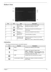
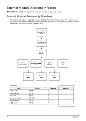
... color may vary from system Remove Battery Remove Dummy Card Remove HDD/WLAN/DIM M Door Remove 3G Cover Remove ODD Remove DIMMs Remove WLAN Remove HDD Screw List Step ODD Module ODD Bracket 3G Cover Logic Lower Door WLAN Module HDD Carrier Screw M 2.5*8 M2*3 M2*3 M2.5*8 M2*3 M3*3 Quantity 1 2 1 2 1 4 Part No. 46...
... color may vary from system Remove Battery Remove Dummy Card Remove HDD/WLAN/DIM M Door Remove 3G Cover Remove ODD Remove DIMMs Remove WLAN Remove HDD Screw List Step ODD Module ODD Bracket 3G Cover Logic Lower Door WLAN Module HDD Carrier Screw M 2.5*8 M2*3 M2*3 M2.5*8 M2*3 M3*3 Quantity 1 2 1 2 1 4 Part No. 46...
Service Guide
Page 62
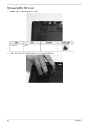
Screw Type 52 Chapter 3 Step 3G Cover Size M2*3 Quantity 1 2. Lift the 3G Cover from the 3G Cover. Remove one (1) screw from the right edge first, then remove completely. Removing the 3G Cover 1.
Screw Type 52 Chapter 3 Step 3G Cover Size M2*3 Quantity 1 2. Lift the 3G Cover from the 3G Cover. Remove one (1) screw from the right edge first, then remove completely. Removing the 3G Cover 1.
Service Guide
Page 68
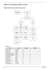
Main Unit Disassembly Process Main Unit Disassembly Flowchart Remove External Modules before proceeding Remove Keyboard Remove Upper Cover Upper Cover Lower Cover Remove Power Board Remove Left Speaker Module Remove Right Speaker Module Remove USB Board Remove TouchPad Bracket Remove ...USB Board Remove Card Reader Board Remove Mainboard Remove Thermal Module Remove CPU Screw List Step Upper Cover Lower Cover Battery Bay Left Speaker Module Right Speaker Module Power Board Card Reader USB Board TouchPad Bracket Mainboard Thermal Module Screw M2.5*5 ...
Main Unit Disassembly Process Main Unit Disassembly Flowchart Remove External Modules before proceeding Remove Keyboard Remove Upper Cover Upper Cover Lower Cover Remove Power Board Remove Left Speaker Module Remove Right Speaker Module Remove USB Board Remove TouchPad Bracket Remove ...USB Board Remove Card Reader Board Remove Mainboard Remove Thermal Module Remove CPU Screw List Step Upper Cover Lower Cover Battery Bay Left Speaker Module Right Speaker Module Power Board Card Reader USB Board TouchPad Bracket Mainboard Thermal Module Screw M2.5*5 ...
Service Guide
Page 69
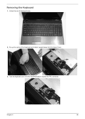
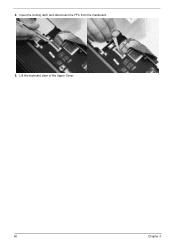
Unlock the six (6) keyboard locks. 2. Chapter 3 59 Turn the keyboard over on to the TouchPad area to expose the FFC connector. Pry up the centre of the Keyboard and rotate it upward away from the Upper Cover. 3. Removing the Keyboard 1.
Unlock the six (6) keyboard locks. 2. Chapter 3 59 Turn the keyboard over on to the TouchPad area to expose the FFC connector. Pry up the centre of the Keyboard and rotate it upward away from the Upper Cover. 3. Removing the Keyboard 1.
Service Guide
Page 70
Open the locking latch and disconnect the FFC from the mainboard. 5. Lift the keyboard clear of the Upper Cover. 60 Chapter 3 4.
Open the locking latch and disconnect the FFC from the mainboard. 5. Lift the keyboard clear of the Upper Cover. 60 Chapter 3 4.
Service Guide
Page 71
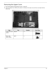
Turn the computer over. Remove the eleven (11) screws on page 46. 2. Step Lower Cover (red callout) Size M2.5*8 Battery Bay (green callout) M2*3 Quantity 11 4 Screw Type Chapter 3 61 See "External Module Disassembly Process" on the lower cover and four (4) screws from the battery bay. Removing the Upper Cover 1.
Turn the computer over. Remove the eleven (11) screws on page 46. 2. Step Lower Cover (red callout) Size M2.5*8 Battery Bay (green callout) M2*3 Quantity 11 4 Screw Type Chapter 3 61 See "External Module Disassembly Process" on the lower cover and four (4) screws from the battery bay. Removing the Upper Cover 1.
Service Guide
Page 74
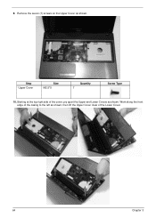
Work along the front edge of the casing to the left as shown, then lift the Upper Cover clear of the cover, pry apart the Upper and Lower Covers as shown. Starting at the top right side of the Lower Cover. 64 Chapter 3 Step Upper Cover Size M2.5*5 Quantity 7 Screw Type 10. 9. Remove the seven (7) screws on the Upper Cover as shown.
Work along the front edge of the casing to the left as shown, then lift the Upper Cover clear of the cover, pry apart the Upper and Lower Covers as shown. Starting at the top right side of the Lower Cover. 64 Chapter 3 Step Upper Cover Size M2.5*5 Quantity 7 Screw Type 10. 9. Remove the seven (7) screws on the Upper Cover as shown.
Service Guide
Page 75
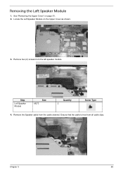
Ensure that the cable is free from the left speaker module. Chapter 3 65 Locate the Left Speaker Module on page 61. 2. Removing the Left Speaker Module 1. Remove two (2) screws from all cable clips. Step Left Speaker Module Size M2*3 Quantity 2 Screw Type 4. See "Removing the Upper Cover" on the Upper Cover as shown. 3. Remove the Speaker cable from the cable channel.
Ensure that the cable is free from the left speaker module. Chapter 3 65 Locate the Left Speaker Module on page 61. 2. Removing the Left Speaker Module 1. Remove two (2) screws from all cable clips. Step Left Speaker Module Size M2*3 Quantity 2 Screw Type 4. See "Removing the Upper Cover" on the Upper Cover as shown. 3. Remove the Speaker cable from the cable channel.
Service Guide
Page 76
Lift the Speaker clear of the Upper Cover. 66 Chapter 3 5.
Lift the Speaker clear of the Upper Cover. 66 Chapter 3 5.
Service Guide
Page 77
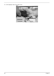
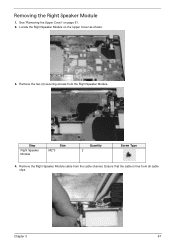
Ensure that the cable is free from the Right Speaker Module. Step Right Speaker Module Size M2*3 Quantity 2 Screw Type 4. Remove the two (2) securing screws from all cable clips. Removing the Right Speaker Module 1. See "Removing the Upper Cover" on the Upper Cover as shown. 3. Chapter 3 67 Locate the Right Speaker Module on page 61. 2. Remove the Right Speaker Module cable from the cable channel.
Ensure that the cable is free from the Right Speaker Module. Step Right Speaker Module Size M2*3 Quantity 2 Screw Type 4. Remove the two (2) securing screws from all cable clips. Removing the Right Speaker Module 1. See "Removing the Upper Cover" on the Upper Cover as shown. 3. Chapter 3 67 Locate the Right Speaker Module on page 61. 2. Remove the Right Speaker Module cable from the cable channel.
Service Guide
Page 79
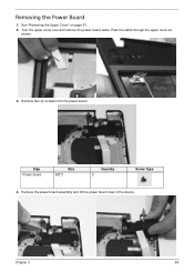
Remove the power board assembly and lift the power board clear of the device. Chapter 3 69 Turn the upper cover over and remove the power board cable. Pass the cable through the upper cover as shown. 3. Remove two (2) screws from the power board. Removing the Power Board 1. See "Removing the Upper Cover" on page 61. 2. Step Power board Size M2*3 Quantity 2 Screw Type 4.
Remove the power board assembly and lift the power board clear of the device. Chapter 3 69 Turn the upper cover over and remove the power board cable. Pass the cable through the upper cover as shown. 3. Remove two (2) screws from the power board. Removing the Power Board 1. See "Removing the Upper Cover" on page 61. 2. Step Power board Size M2*3 Quantity 2 Screw Type 4.
Service Guide
Page 80
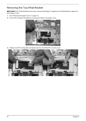
To replace the TouchPad Board, replace the entire Upper Cover. 1. See "Removing the Upper Cover" on page 61. 2. Lift the FFC to detach the adhesive securing the cable to the Upper Cover. 3. Release the FFC locking latch and disconnect the TouchPad FFC from the cover. 70 Chapter 3 Removing the TouchPad Bracket IMPORTANT: The TouchPad Board cannot be removed individually.
To replace the TouchPad Board, replace the entire Upper Cover. 1. See "Removing the Upper Cover" on page 61. 2. Lift the FFC to detach the adhesive securing the cable to the Upper Cover. 3. Release the FFC locking latch and disconnect the TouchPad FFC from the cover. 70 Chapter 3 Removing the TouchPad Bracket IMPORTANT: The TouchPad Board cannot be removed individually.


