Quick Start Guide
Page 7
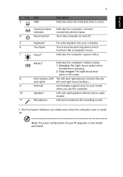
...) left and right buttons function like a computer mouse. 7 Power1 Indicates the computer's power status. Communication indicator Indicates the computer's wireless connectivity device status. 4 Power button Turns the computer on the model purchased. Charging: The light shows amber when the battery is closed up. The front panel indicators are visible even when...
...) left and right buttons function like a computer mouse. 7 Power1 Indicates the computer's power status. Communication indicator Indicates the computer's wireless connectivity device status. 4 Power button Turns the computer on the model purchased. Charging: The light shows amber when the battery is closed up. The front panel indicators are visible even when...
Quick Start Guide
Page 8
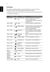
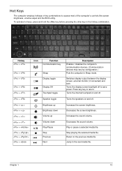
... disables the computer's key communication devices. (Communication devices may vary by configuration.) Sleep Puts the computer in the hotkey combination. Turns the internal touchpad on and off . Previous Return to access most of the computer's controls like screen brightness and volume output. ...hold the key before pressing the other key in Sleep mode. + + + + Display toggle Display off to save power. Turns the display screen backlight off Touchpad toggle Speaker toggle Switches display output between the display screen, external monitor (if connected) and ...
... disables the computer's key communication devices. (Communication devices may vary by configuration.) Sleep Puts the computer in the hotkey combination. Turns the internal touchpad on and off . Previous Return to access most of the computer's controls like screen brightness and volume output. ...hold the key before pressing the other key in Sleep mode. + + + + Display toggle Display off to save power. Turns the display screen backlight off Touchpad toggle Speaker toggle Switches display output between the display screen, external monitor (if connected) and ...
Quick Start Guide
Page 10
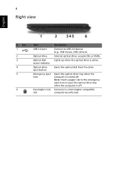
... lock slot Description Connect to USB 2.0 devices (e.g., USB mouse, USB camera). accepts CDs or DVDs. Internal optical drive; Lights up when the optical drive is turned off .
... lock slot Description Connect to USB 2.0 devices (e.g., USB mouse, USB camera). accepts CDs or DVDs. Internal optical drive; Lights up when the optical drive is turned off .
Service Guide
Page 16
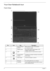
Communication indicator Power button Indicates the computer's wireless connectivitoy device status. Keyboard TouchPad For entering data into your computer. Also called Liquid-Crystal Display (LCD), displays computer output. Your Acer Notebook tour Front View No. 1 2 3 4 5 6 Icon Item Acer Crystal Eye webcam Display screen HDD Description Web camera for video communication (for selected models). Indicates when the hard disk drive is active. Turns the computer on and off. Touch-sensitive pointing device which functions like a computer mouse. 6 Chapter 1
Communication indicator Power button Indicates the computer's wireless connectivitoy device status. Keyboard TouchPad For entering data into your computer. Also called Liquid-Crystal Display (LCD), displays computer output. Your Acer Notebook tour Front View No. 1 2 3 4 5 6 Icon Item Acer Crystal Eye webcam Display screen HDD Description Web camera for video communication (for selected models). Indicates when the hard disk drive is active. Turns the computer on and off. Touch-sensitive pointing device which functions like a computer mouse. 6 Chapter 1
Service Guide
Page 18
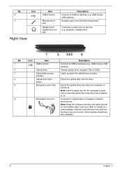
speakers, headphones). accepts CDs or DVDs. Accepts input from the drive. Ejects the optical drive tray when the computer is turned off . Note: Wrap the computer security lock cable around an immovable object such as a table or handle of a locked drawer. USB mouse, USB camera). Lights ... Kensington lock slot Description Connect to audio line-out devices (e.g. Ejects the optical disk from external microphones. Note: Insert a paper clip into the notch and turn the key to eject the optical drive tray when the computer is active. Internal optical drive;
speakers, headphones). accepts CDs or DVDs. Accepts input from the drive. Ejects the optical drive tray when the computer is turned off . Note: Wrap the computer security lock cable around an immovable object such as a table or handle of a locked drawer. USB mouse, USB camera). Lights ... Kensington lock slot Description Connect to audio line-out devices (e.g. Ejects the optical disk from external microphones. Note: Insert a paper clip into the notch and turn the key to eject the optical drive tray when the computer is active. Internal optical drive;
Service Guide
Page 23
.... Increases the sound volume. Decreases the sound volume. Return to the next media file. Jump to the previous media file. Chapter 1 13 Turns the internal touchpad on and off. Turns the speakers on and off to save power. Stop playing the selected media file. Switches display output between the display screen, external...
.... Increases the sound volume. Decreases the sound volume. Return to the next media file. Jump to the previous media file. Chapter 1 13 Turns the internal touchpad on and off. Turns the speakers on and off to save power. Stop playing the selected media file. Switches display output between the display screen, external...
Service Guide
Page 28
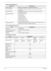
Individual devices such as the CPU and hard disk may be power managed in the system are turned off completely. Hard Disk Drive Interface Item Vendor/model name Seagate Capacity (MB) 160, 250, 320, 500 Bytes per sector Data heads Drive Format Disks ... 160, 250, 320, 500, 640 1-2 5400 8 MB SATA 5V ±5% Samsung 160, 250, 320 18 Chapter 1 OS initiated shutdown. All devices in the system are turned off the whole system. System Saves all system states and data onto disk prior to power off completely. CPU set power down VGA Suspend PCMCIA...
Individual devices such as the CPU and hard disk may be power managed in the system are turned off completely. Hard Disk Drive Interface Item Vendor/model name Seagate Capacity (MB) 160, 250, 320, 500 Bytes per sector Data heads Drive Format Disks ... 160, 250, 320, 500, 640 1-2 5400 8 MB SATA 5V ±5% Samsung 160, 250, 320 18 Chapter 1 OS initiated shutdown. All devices in the system are turned off the whole system. System Saves all system states and data onto disk prior to power off completely. CPU set power down VGA Suspend PCMCIA...
Service Guide
Page 38
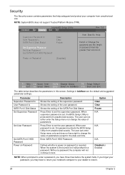
... on Password Description Shows the setting of the supervisor password Shows the setting of parameters except for a password. Defines whether a power on password is first turned on Password [Disabled] F1 Help ESC Exit Select Item F5/F6 Change Values F9 Setup Default Select Menu Enter Select SubMenu F10 Save and Exit...
... on Password Description Shows the setting of the supervisor password Shows the setting of parameters except for a password. Defines whether a power on password is first turned on Password [Disabled] F1 Help ESC Exit Select Item F5/F6 Change Values F9 Setup Default Select Menu Enter Select SubMenu F10 Save and Exit...
Service Guide
Page 54
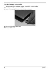
Pre-disassembly Instructions Before proceeding with the disassembly procedure, make sure that you do the following: 1. Remove the battery pack. 44 Chapter 3 Unplug the AC adapter and all peripherals. 2. Place the system on a flat, stable surface. 4. Turn off the power to the system and all power and signal cables from the system. 3.
Pre-disassembly Instructions Before proceeding with the disassembly procedure, make sure that you do the following: 1. Remove the battery pack. 44 Chapter 3 Unplug the AC adapter and all peripherals. 2. Place the system on a flat, stable surface. 4. Turn off the power to the system and all power and signal cables from the system. 3.
Service Guide
Page 56
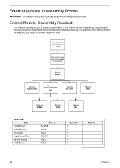
For example, if you want to remove the keyboard, you on the components that need to be removed during servicing. Turn off system and peripherals power Disconnect power and signal cables from the mass produced model. External Modules Disassembly Flowchart The flowchart below gives you a graphic ...
For example, if you want to remove the keyboard, you on the components that need to be removed during servicing. Turn off system and peripherals power Disconnect power and signal cables from the mass produced model. External Modules Disassembly Flowchart The flowchart below gives you a graphic ...
Service Guide
Page 57
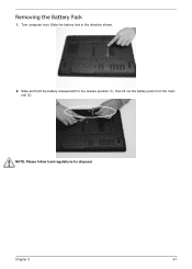
Removing the Battery Pack 1. Slide the battery lock in the direction shown. 2. Chapter 3 47 Slide and hold the battery release latch to the release position (1), then lift out the battery pack from the main unit (2). 2 1 NOTE: Please follow local regulations for disposal. Turn computer over.
Removing the Battery Pack 1. Slide the battery lock in the direction shown. 2. Chapter 3 47 Slide and hold the battery release latch to the release position (1), then lift out the battery pack from the main unit (2). 2 1 NOTE: Please follow local regulations for disposal. Turn computer over.
Service Guide
Page 69
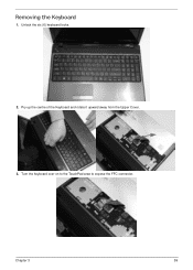
Pry up the centre of the Keyboard and rotate it upward away from the Upper Cover. 3. Turn the keyboard over on to the TouchPad area to expose the FFC connector. Chapter 3 59 Unlock the six (6) keyboard locks. 2. Removing the Keyboard 1.
Pry up the centre of the Keyboard and rotate it upward away from the Upper Cover. 3. Turn the keyboard over on to the TouchPad area to expose the FFC connector. Chapter 3 59 Unlock the six (6) keyboard locks. 2. Removing the Keyboard 1.
Service Guide
Page 71
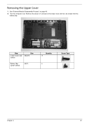
Step Lower Cover (red callout) Size M2.5*8 Battery Bay (green callout) M2*3 Quantity 11 4 Screw Type Chapter 3 61 See "External Module Disassembly Process" on the lower cover and four (4) screws from the battery bay. Remove the eleven (11) screws on page 46. 2. Removing the Upper Cover 1. Turn the computer over.
Step Lower Cover (red callout) Size M2.5*8 Battery Bay (green callout) M2*3 Quantity 11 4 Screw Type Chapter 3 61 See "External Module Disassembly Process" on the lower cover and four (4) screws from the battery bay. Remove the eleven (11) screws on page 46. 2. Removing the Upper Cover 1. Turn the computer over.
Service Guide
Page 72
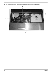
Turn the computer over and disconnect the following four (4) cables from the Mainboard. 3. B C A D 62 Chapter 3
Turn the computer over and disconnect the following four (4) cables from the Mainboard. 3. B C A D 62 Chapter 3
Service Guide
Page 79
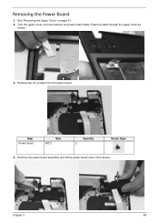
Remove the power board assembly and lift the power board clear of the device. Step Power board Size M2*3 Quantity 2 Screw Type 4. Remove two (2) screws from the power board. See "Removing the Upper Cover" on page 61. 2. Pass the cable through the upper cover as shown. 3. Turn the upper cover over and remove the power board cable. Chapter 3 69 Removing the Power Board 1.
Remove the power board assembly and lift the power board clear of the device. Step Power board Size M2*3 Quantity 2 Screw Type 4. Remove two (2) screws from the power board. See "Removing the Upper Cover" on page 61. 2. Pass the cable through the upper cover as shown. 3. Turn the upper cover over and remove the power board cable. Chapter 3 69 Removing the Power Board 1.
Service Guide
Page 88
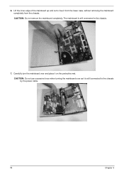
CAUTION: Do not use excessive force when turning the mainboard over and place it on the protective mat. Lift the inner edge of the mainboard up and out to free it is still connected to the chassis by the power cable. 78 Chapter 3 CAUTION: Do not remove the mainboard completely. The mainboard is still connected to the chassis. 7. 6. Carefully turn the mainboard over as it from the lower case, without removing the mainboard completely from the chassis.
CAUTION: Do not use excessive force when turning the mainboard over and place it on the protective mat. Lift the inner edge of the mainboard up and out to free it is still connected to the chassis by the power cable. 78 Chapter 3 CAUTION: Do not remove the mainboard completely. The mainboard is still connected to the chassis. 7. 6. Carefully turn the mainboard over as it from the lower case, without removing the mainboard completely from the chassis.
Service Guide
Page 89
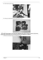
Disconnect the power cable. 9. Please detach the Circuit board and follow local regulations for disposal. 10. NOTE: Circuit boards >10 cm² have been highlighted with a yellow rectangle as shown in the previous image. 8. Chapter 3 79 Remove the adhesive tape from the chassis and turn it over. Remove the mainboard from the Bluetooth cable.
Disconnect the power cable. 9. Please detach the Circuit board and follow local regulations for disposal. 10. NOTE: Circuit boards >10 cm² have been highlighted with a yellow rectangle as shown in the previous image. 8. Chapter 3 79 Remove the adhesive tape from the chassis and turn it over. Remove the mainboard from the Bluetooth cable.
Service Guide
Page 95
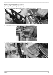
See "Removing the Upper Cover" on page 61. 2. Turn the device over and pass the black and white antenna cables through the lower cover. 3. Free the black and white antenna cables from the cable channel. Chapter 3 85 Removing the LCD Assembly 1. Continue removing the white antenna cable from the cable channel as shown. 4.
See "Removing the Upper Cover" on page 61. 2. Turn the device over and pass the black and white antenna cables through the lower cover. 3. Free the black and white antenna cables from the cable channel. Chapter 3 85 Removing the LCD Assembly 1. Continue removing the white antenna cable from the cable channel as shown. 4.
Service Guide
Page 102
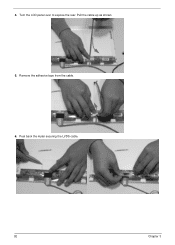
Turn the LCD panel over to expose the rear. Remove the adhesive tape from the cable. 6. Peel back the mylar securing the LVDS cable. 92 Chapter 3 4. Pull the cable up as shown. 5.
Turn the LCD panel over to expose the rear. Remove the adhesive tape from the cable. 6. Peel back the mylar securing the LVDS cable. 92 Chapter 3 4. Pull the cable up as shown. 5.
Service Guide
Page 136
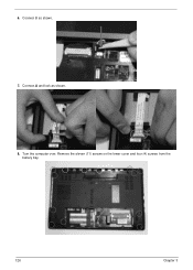
Turn the computer over. Remove the eleven (11) screws on the lower cover and four (4) screws from the battery bay. 126 Chapter 3 Connect B as shown. 8. Connect A and lock as shown. 7. 6.
Turn the computer over. Remove the eleven (11) screws on the lower cover and four (4) screws from the battery bay. 126 Chapter 3 Connect B as shown. 8. Connect A and lock as shown. 7. 6.


