Quick Start Guide
Page 7
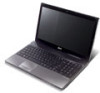
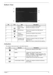
...Speakers Left and right speakers deliver stereo audio output. 11 Microphone Internal microphone for recording sound. 1. Charging: The light shows amber when the battery is active. Note: The exact configuration of your PC depends on and off. 5 Keyboard For entering data into your computer. 6 Touchpad Touch... Indicates the computer's wireless connectivity device status. 4 Power button Turns the computer on the model purchased. Battery1 Indicates the computer's battery status. 1. The front panel indicators are visible even when the computer cover is closed up.
...Speakers Left and right speakers deliver stereo audio output. 11 Microphone Internal microphone for recording sound. 1. Charging: The light shows amber when the battery is active. Note: The exact configuration of your PC depends on and off. 5 Keyboard For entering data into your computer. 6 Touchpad Touch... Indicates the computer's wireless connectivity device status. 4 Power button Turns the computer on the model purchased. Battery1 Indicates the computer's battery status. 1. The front panel indicators are visible even when the computer cover is closed up.
Quick Start Guide
Page 11
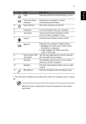
.... Houses the computer's main memory. Ventilation slots and cooling fan Enable the computer to 80% Releases the battery for removal. Environment • Temperature: • Operating: 5 °C to 35 °C • Non-operating: -20 °C to 65 °C • Humidity (non-condensing): • Operating: ..., even after prolonged use. Note: Do not cover or obstruct the opening of the fan. Houses the computer's hard disk (secured with screws). Locks the battery in position.
.... Houses the computer's main memory. Ventilation slots and cooling fan Enable the computer to 80% Releases the battery for removal. Environment • Temperature: • Operating: 5 °C to 35 °C • Non-operating: -20 °C to 65 °C • Humidity (non-condensing): • Operating: ..., even after prolonged use. Note: Do not cover or obstruct the opening of the fan. Houses the computer's hard disk (secured with screws). Locks the battery in position.
Service Guide
Page 7
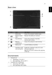
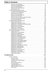
Table of Contents System Specifications 1 Features 1 System Block Diagram 5 Your Acer Notebook tour 6 Front View 6 Closed Front View 7 Left View 7 Right ... Specifications and Configurations 14 System Utilities 25 BIOS Setup Utility 25 Navigating the BIOS Utility 25 Aspire 5251/5551G/5551 BIOS 26 Information 26 Main 27 Security 28 Boot 31 Exit 32 BIOS Flash... 44 Disassembly Process 45 External Module Disassembly Process 46 External Modules Disassembly Flowchart 46 Removing the Battery Pack 47 Removing the SD Dummy Card 48 Removing the Optical Drive Module 49 Removing the...
Table of Contents System Specifications 1 Features 1 System Block Diagram 5 Your Acer Notebook tour 6 Front View 6 Closed Front View 7 Left View 7 Right ... Specifications and Configurations 14 System Utilities 25 BIOS Setup Utility 25 Navigating the BIOS Utility 25 Aspire 5251/5551G/5551 BIOS 26 Information 26 Main 27 Security 28 Boot 31 Exit 32 BIOS Flash... 44 Disassembly Process 45 External Module Disassembly Process 46 External Modules Disassembly Flowchart 46 Removing the Battery Pack 47 Removing the SD Dummy Card 48 Removing the Optical Drive Module 49 Removing the...
Service Guide
Page 8
... 130 Replacing the 3G Cover 131 Replacing the Logic Lower Door 132 Replacing the ODD Module 133 Replacing the SD Dummy Card 134 Replacing the Battery 135 Troubleshooting 137 Common Problems 137 Power On Issue 138 No Display Issue 139 Random Loss of BIOS Settings 140 LCD Failure 141 Built-In...
... 130 Replacing the 3G Cover 131 Replacing the Logic Lower Door 132 Replacing the ODD Module 133 Replacing the SD Dummy Card 134 Replacing the Battery 135 Troubleshooting 137 Common Problems 137 Power On Issue 138 No Display Issue 139 Random Loss of BIOS Settings 140 LCD Failure 141 Built-In...
Service Guide
Page 13
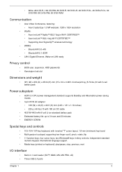
...8X DVD+RW, 5X DVD-RAM Communication • Acer Video Conference, featuring: • Acer Crystal Eye 1.3 MP webcam, 1280 x 1024 resolution • WLAN: • Acer InviLink™ Nplify™ 802.11b/g/n Wi-Fi CERTIFIED™ • Acer InviLink™ 802.11b/g Wi-Fi CERTIFIED™...slot Dimensions and weight • 381 (W) x 253 (D) x 25/34 (H) mm (15 x 9.9 x 0.98/1.3 inches)2.6 kg (5.74 lbs.)10 with 6-cell battery pack Power subsystem • ACPI 3.0 CPU power management standard: supports Standby and Hibernation power-saving modes • 3-pin 65 W AC adapter: • 108 (W) x...
...8X DVD+RW, 5X DVD-RAM Communication • Acer Video Conference, featuring: • Acer Crystal Eye 1.3 MP webcam, 1280 x 1024 resolution • WLAN: • Acer InviLink™ Nplify™ 802.11b/g/n Wi-Fi CERTIFIED™ • Acer InviLink™ 802.11b/g Wi-Fi CERTIFIED™...slot Dimensions and weight • 381 (W) x 253 (D) x 25/34 (H) mm (15 x 9.9 x 0.98/1.3 inches)2.6 kg (5.74 lbs.)10 with 6-cell battery pack Power subsystem • ACPI 3.0 CPU power management standard: supports Standby and Hibernation power-saving modes • 3-pin 65 W AC adapter: • 108 (W) x...
Service Guide
Page 14
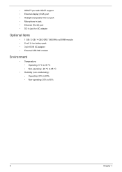
... (RJ-45) port • DC-in jack for AC adapter Optional Items • 1 GB / 2 GB / 4 GB DDR3 1066 MHz soDIMM module • 6-cell Li-ion battery pack • 3-pin 65 W AC adapter • External USB 56K modem Environment • Temperature: • Operating: 5 °C to 35 °C • Non-operating: -20 °...
... (RJ-45) port • DC-in jack for AC adapter Optional Items • 1 GB / 2 GB / 4 GB DDR3 1066 MHz soDIMM module • 6-cell Li-ion battery pack • 3-pin 65 W AC adapter • External USB 56K modem Environment • Temperature: • Operating: 5 °C to 35 °C • Non-operating: -20 °...

Service Guide
Page 17
The left and right buttons function like the left and right) Palmrest Speakers Microphone Indicates the computer's battery status. 1. Comfortable support area for recording sound. Internal microphone for your hands when you use . Connect to remove/install the card.... operate at any given time. No. 7 8 9 10 11 Icon Item Power1 Description Indicates the computer's power status. Charging: The light shows amber when the battery is closed. No. 1 2 3 4 5 Chapter 1 Icon Item DC-in jack Ventilation slots External display (VGA) port Ethernet (RJ-45) port HDMI Description...
The left and right buttons function like the left and right) Palmrest Speakers Microphone Indicates the computer's battery status. 1. Comfortable support area for recording sound. Internal microphone for your hands when you use . Connect to remove/install the card.... operate at any given time. No. 7 8 9 10 11 Icon Item Power1 Description Indicates the computer's power status. Charging: The light shows amber when the battery is closed. No. 1 2 3 4 5 Chapter 1 Icon Item DC-in jack Ventilation slots External display (VGA) port Ethernet (RJ-45) port HDMI Description...
Service Guide
Page 19
... easy-to stay cool, even after and cooling fan prolonged use. Charging: The light shows amber when the battery is active. Houses the computer's hard disk (secured with screws). Battery HDD Indicates the computer's battery status. Communication indicator Indicates the computer's wireless connectivitoy device status. Icon Function Power Description Indicates the computer's power...
... easy-to stay cool, even after and cooling fan prolonged use. Charging: The light shows amber when the battery is active. Houses the computer's hard disk (secured with screws). Battery HDD Indicates the computer's battery status. Communication indicator Indicates the computer's wireless connectivitoy device status. Icon Function Power Description Indicates the computer's power...
Service Guide
Page 24
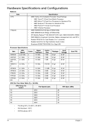
... SB820M South Bridge uFCBGA-605p • ATI Mobility Radeon™ HD 5650/5470 GPU with 1GB/512M DDR3 VRAM • ENE KB926 for Keyboard Controller, Battery management Unit, and RTC. • Realtek RTS5160 for Card Reader, 5 in 1 controller. • Realtek ALC272-X for High Definition Audio Codec. • Broadcom ...2 MB 2 MB 2 MB Package S1g4 S1g4 S1g4 S1g4 S1g4 S1g4 S1g4 S1g4 S1g4 Core Voltage 35 W 25 W 25 W 25 W 35 W 35 W 35 W 25 W 25 W Acer P/N CPU Fan True Value Table (Tj = 100 DIS) CPU Temp (°C) Core 0 Fan Speed (rpm) 50 2500 56 2900 63 3200 70 3600 80 4000...
... SB820M South Bridge uFCBGA-605p • ATI Mobility Radeon™ HD 5650/5470 GPU with 1GB/512M DDR3 VRAM • ENE KB926 for Keyboard Controller, Battery management Unit, and RTC. • Realtek RTS5160 for Card Reader, 5 in 1 controller. • Realtek ALC272-X for High Definition Audio Codec. • Broadcom ...2 MB 2 MB 2 MB Package S1g4 S1g4 S1g4 S1g4 S1g4 S1g4 S1g4 S1g4 S1g4 Core Voltage 35 W 25 W 25 W 25 W 35 W 35 W 35 W 25 W 25 W Acer P/N CPU Fan True Value Table (Tj = 100 DIS) CPU Temp (°C) Core 0 Fan Speed (rpm) 50 2500 56 2900 63 3200 70 3600 80 4000...
Service Guide
Page 27
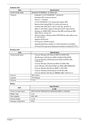
Onboard LAN Item Vendor/model name Features Wireless LAN Item Vendor/model name Protocol Interface Antenna Battery Item Vendor & model name Battery Type Pack capacity Normal Voltage Package configuration Specification Broadcom 57780KMLG for GIGA LAN • Integrated 10/100/10000BASE-T transceiver • Automatic MDI crossover function • ...
Onboard LAN Item Vendor/model name Features Wireless LAN Item Vendor/model name Protocol Interface Antenna Battery Item Vendor & model name Battery Type Pack capacity Normal Voltage Package configuration Specification Broadcom 57780KMLG for GIGA LAN • Integrated 10/100/10000BASE-T transceiver • Automatic MDI crossover function • ...
Service Guide
Page 43
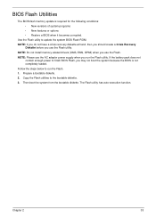
...: If you do not have a crisis recovery diskette at hand, then you should create a Crisis Recovery Diskette before you use the Flash utility. If the battery pack does not contain enough power to run the Flash utility. NOTE: Do not install memory-related drivers (XMS, EMS, DPMI) when you use the...
...: If you do not have a crisis recovery diskette at hand, then you should create a Crisis Recovery Diskette before you use the Flash utility. If the battery pack does not contain enough power to run the Flash utility. NOTE: Do not install memory-related drivers (XMS, EMS, DPMI) when you use the...
Service Guide
Page 54
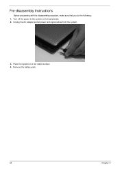
Remove the battery pack. 44 Chapter 3 Unplug the AC adapter and all peripherals. 2. Place the system on a flat, stable surface. 4. Turn off the power to the system and all power and signal cables from the system. 3. Pre-disassembly Instructions Before proceeding with the disassembly procedure, make sure that you do the following: 1.
Remove the battery pack. 44 Chapter 3 Unplug the AC adapter and all peripherals. 2. Place the system on a flat, stable surface. 4. Turn off the power to the system and all power and signal cables from the system. 3. Pre-disassembly Instructions Before proceeding with the disassembly procedure, make sure that you do the following: 1.
Service Guide
Page 56
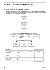
... on the components that need to be removed during servicing. External Module Disassembly Process IMPORTANT: The outside housing and color may vary from system Remove Battery Remove Dummy Card Remove HDD/WLAN/DIM M Door Remove 3G Cover Remove ODD Remove DIMMs Remove WLAN Remove HDD Screw List Step ODD Module ODD...
... on the components that need to be removed during servicing. External Module Disassembly Process IMPORTANT: The outside housing and color may vary from system Remove Battery Remove Dummy Card Remove HDD/WLAN/DIM M Door Remove 3G Cover Remove ODD Remove DIMMs Remove WLAN Remove HDD Screw List Step ODD Module ODD...
Service Guide
Page 57
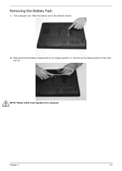
Turn computer over. Slide and hold the battery release latch to the release position (1), then lift out the battery pack from the main unit (2). 2 1 NOTE: Please follow local regulations for disposal. Slide the battery lock in the direction shown. 2. Chapter 3 47 Removing the Battery Pack 1.
Turn computer over. Slide and hold the battery release latch to the release position (1), then lift out the battery pack from the main unit (2). 2 1 NOTE: Please follow local regulations for disposal. Slide the battery lock in the direction shown. 2. Chapter 3 47 Removing the Battery Pack 1.
Service Guide
Page 59
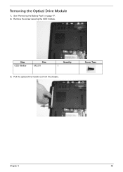
Remove the screw securing the ODD module. Pull the optical drive module out from the chassis. Screw Type Chapter 3 49 See "Removing the Battery Pack" on page 47. 2. Step ODD Module Size M2.5*8 Quantity 1 3. Removing the Optical Drive Module 1.
Remove the screw securing the ODD module. Pull the optical drive module out from the chassis. Screw Type Chapter 3 49 See "Removing the Battery Pack" on page 47. 2. Step ODD Module Size M2.5*8 Quantity 1 3. Removing the Optical Drive Module 1.
Service Guide
Page 68
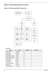
... Board Remove TouchPad Bracket Remove USB Board Remove Card Reader Board Remove Mainboard Remove Thermal Module Remove CPU Screw List Step Upper Cover Lower Cover Battery Bay Left Speaker Module Right Speaker Module Power Board Card Reader USB Board TouchPad Bracket Mainboard Thermal Module Screw M2.5*5 M2.5*8 M2*3 M2*3 M2*3 M2...
... Board Remove TouchPad Bracket Remove USB Board Remove Card Reader Board Remove Mainboard Remove Thermal Module Remove CPU Screw List Step Upper Cover Lower Cover Battery Bay Left Speaker Module Right Speaker Module Power Board Card Reader USB Board TouchPad Bracket Mainboard Thermal Module Screw M2.5*5 M2.5*8 M2*3 M2*3 M2*3 M2...
Service Guide
Page 71
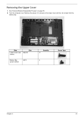
See "External Module Disassembly Process" on the lower cover and four (4) screws from the battery bay. Turn the computer over. Remove the eleven (11) screws on page 46. 2. Step Lower Cover (red callout) Size M2.5*8 Battery Bay (green callout) M2*3 Quantity 11 4 Screw Type Chapter 3 61 Removing the Upper Cover 1.
See "External Module Disassembly Process" on the lower cover and four (4) screws from the battery bay. Turn the computer over. Remove the eleven (11) screws on page 46. 2. Step Lower Cover (red callout) Size M2.5*8 Battery Bay (green callout) M2*3 Quantity 11 4 Screw Type Chapter 3 61 Removing the Upper Cover 1.
Service Guide
Page 136
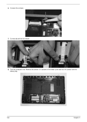
Connect A and lock as shown. 7. 6. Connect B as shown. 8. Turn the computer over. Remove the eleven (11) screws on the lower cover and four (4) screws from the battery bay. 126 Chapter 3
Connect A and lock as shown. 7. 6. Connect B as shown. 8. Turn the computer over. Remove the eleven (11) screws on the lower cover and four (4) screws from the battery bay. 126 Chapter 3
Service Guide
Page 145
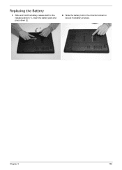
Replacing the Battery 1. Slide and hold the battery release latch to secure the battery in the direction shown to the release position (1), insert the battery pack and press down (2). 2. Slide the battery lock in place. 2 1 Chapter 3 135
Replacing the Battery 1. Slide and hold the battery release latch to secure the battery in the direction shown to the release position (1), insert the battery pack and press down (2). 2. Slide the battery lock in place. 2 1 Chapter 3 135
Service Guide
Page 149
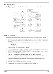
... the internal display and the external display is done by checking at least one until the failure point is by removing the power cable and battery and holding down the power button for specific model procedures. 2. Remove the drives (see "Online Support Information" on page 138. 3. If the POST or video...
... the internal display and the external display is done by checking at least one until the failure point is by removing the power cable and battery and holding down the power button for specific model procedures. 2. Remove the drives (see "Online Support Information" on page 138. 3. If the POST or video...


