Quick Start Guide
Page 5
... certain models of your new computer. The Quick Guide introduces you get started with language such as system utilities, data recovery, expansion options and troubleshooting. If Adobe Reader is available in the text with setting up your computer. For more productive, please refer to the AcerSystem User Guide. Note: Viewing the file requires Adobe Reader. For instructions on how your computer can help you use Adobe Reader, access...
... certain models of your new computer. The Quick Guide introduces you get started with language such as system utilities, data recovery, expansion options and troubleshooting. If Adobe Reader is available in the text with setting up your computer. For more productive, please refer to the AcerSystem User Guide. Note: Viewing the file requires Adobe Reader. For instructions on how your computer can help you use Adobe Reader, access...
Quick Start Guide
Page 7
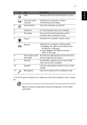
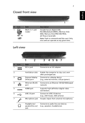
... exact configuration of your hands when you use the computer. 10 Speakers Left and right speakers deliver stereo audio output. 11 Microphone Internal microphone for your PC depends on and off. 5 Keyboard For entering data into your computer. 6 Touchpad Touch-sensitive pointing device which functions like the and right) left and right mouse buttons. 9 Palmrest Comfortable support area for recording sound. 1. Communication indicator Indicates the computer's wireless connectivity device status. 4 Power button Turns the...
... exact configuration of your hands when you use the computer. 10 Speakers Left and right speakers deliver stereo audio output. 11 Microphone Internal microphone for your PC depends on and off. 5 Keyboard For entering data into your computer. 6 Touchpad Touch-sensitive pointing device which functions like the and right) left and right mouse buttons. 9 Palmrest Comfortable support area for recording sound. 1. Communication indicator Indicates the computer's wireless connectivity device status. 4 Power button Turns the...
Quick Start Guide
Page 8
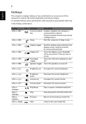
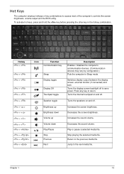
... other key in Sleep mode. + + + + Display toggle Display off . Press any key to the next media file. Increases the sound volume. Volume down Volume up Decreases the screen brightness. Next Jump to return. Hotkey + + Icon Function Description Communication Enables / disables the computer's key communication devices. (Communication devices may vary by configuration.) Sleep Puts the computer in the hotkey combination. Turns the speakers on and off Touchpad toggle Speaker toggle Switches display output between the display screen, external monitor (if connected...
... other key in Sleep mode. + + + + Display toggle Display off . Press any key to the next media file. Increases the sound volume. Volume down Volume up Decreases the screen brightness. Next Jump to return. Hotkey + + Icon Function Description Communication Enables / disables the computer's key communication devices. (Communication devices may vary by configuration.) Sleep Puts the computer in the hotkey combination. Turns the speakers on and off Touchpad toggle Speaker toggle Switches display output between the display screen, external monitor (if connected...
Quick Start Guide
Page 9
..., headphones). Accepts inputs from external microphones. Headphones/ speaker/line-out jack Connects to a display device (e.g., external monitor, LCD projector). Ventilation slots External display (VGA) port Enable the computer to an Ethernet 10/100/1000-based port network. Ethernet (RJ-45) Connects to stay cool, even after prolonged use. Note: Push to USB 2.0 devices (e.g., USB mouse, USB camera). HDMI port USB 2.0 port Microphone jack Supports high definition digital video connections. Connect to remove/install the card. Only one card can operate at any given time...
..., headphones). Accepts inputs from external microphones. Headphones/ speaker/line-out jack Connects to a display device (e.g., external monitor, LCD projector). Ventilation slots External display (VGA) port Enable the computer to an Ethernet 10/100/1000-based port network. Ethernet (RJ-45) Connects to stay cool, even after prolonged use. Note: Push to USB 2.0 devices (e.g., USB mouse, USB camera). HDMI port USB 2.0 port Microphone jack Supports high definition digital video connections. Connect to remove/install the card. Only one card can operate at any given time...
Service Guide
Page 7
...View 9 Indicators 9 TouchPad Basics 10 Using the Keyboard 11 Lock Keys and embedded numeric keypad 11 Windows Keys 12 Hot Keys 13 Hardware Specifications and Configurations 14 System Utilities 25 BIOS Setup Utility 25 Navigating the BIOS Utility 25 Aspire 5251/5551G/5551 BIOS 26 Information 26 Main 27 Security 28 Boot 31 Exit 32 BIOS Flash Utilities 33 DOS Flash Utility 34 WinFlash Utility 36 Remove HDD/BIOS Password Utilities 37 Machine Disassembly and Replacement 43 Disassembly Requirements 43 Pre-disassembly Instructions 44 Disassembly Process 45 External Module...
...View 9 Indicators 9 TouchPad Basics 10 Using the Keyboard 11 Lock Keys and embedded numeric keypad 11 Windows Keys 12 Hot Keys 13 Hardware Specifications and Configurations 14 System Utilities 25 BIOS Setup Utility 25 Navigating the BIOS Utility 25 Aspire 5251/5551G/5551 BIOS 26 Information 26 Main 27 Security 28 Boot 31 Exit 32 BIOS Flash Utilities 33 DOS Flash Utility 34 WinFlash Utility 36 Remove HDD/BIOS Password Utilities 37 Machine Disassembly and Replacement 43 Disassembly Requirements 43 Pre-disassembly Instructions 44 Disassembly Process 45 External Module...
Service Guide
Page 8
... Keyboard 127 Replacing the Hard Disk Drive Module 128 Replacing the WLAN Module 129 Replacing the DIMM Modules 130 Replacing the 3G Cover 131 Replacing the Logic Lower Door 132 Replacing the ODD Module 133 Replacing the SD Dummy Card 134 Replacing the Battery 135 Troubleshooting 137 Common Problems 137 Power On Issue 138 No Display Issue 139 Random Loss of BIOS Settings 140 LCD Failure 141 Built-In Keyboard Failure 141 TouchPad Failure 142 Internal Speaker Failure 142 HDD...
... Keyboard 127 Replacing the Hard Disk Drive Module 128 Replacing the WLAN Module 129 Replacing the DIMM Modules 130 Replacing the 3G Cover 131 Replacing the Logic Lower Door 132 Replacing the ODD Module 133 Replacing the SD Dummy Card 134 Replacing the Battery 135 Troubleshooting 137 Common Problems 137 Power On Issue 138 No Display Issue 139 Random Loss of BIOS Settings 140 LCD Failure 141 Built-In Keyboard Failure 141 TouchPad Failure 142 Internal Speaker Failure 142 HDD...

Service Guide
Page 17
...'s power status. Comfortable support area for recording sound. Connects to remove/install the card. Battery1 Click buttons (left and right mouse buttons. Charging: The light shows amber when the battery is closed. Left and right speakers deliver stereo audio output. NOTE: 1 The front panel indicators are visible even when the computer cover is charging. 2. Internal microphone for your hands when you use . Only one card can operate at any given time. external monitor, LCD projector). Connects to HDMI devices 7 Connect...
...'s power status. Comfortable support area for recording sound. Connects to remove/install the card. Battery1 Click buttons (left and right mouse buttons. Charging: The light shows amber when the battery is closed. Left and right speakers deliver stereo audio output. NOTE: 1 The front panel indicators are visible even when the computer cover is charging. 2. Internal microphone for your hands when you use . Only one card can operate at any given time. external monitor, LCD projector). Connects to HDMI devices 7 Connect...
Service Guide
Page 23
... selected media file. Switches display output between the display screen, external monitor (if connected) and both. Turns the speakers on and off . Return to save power. Play or pause a selected media file. Hot Keys The computer employs hotkeys or key combinations to the next media file. Decreases the screen brightness. Turns the internal touchpad on and off . Chapter 1 13 Jump to access most of the computer's controls like screen brightness, volume output and the BIOS utility. Press any key...
... selected media file. Switches display output between the display screen, external monitor (if connected) and both. Turns the speakers on and off . Return to save power. Play or pause a selected media file. Hot Keys The computer employs hotkeys or key combinations to the next media file. Decreases the screen brightness. Turns the internal touchpad on and off . Chapter 1 13 Jump to access most of the computer's controls like screen brightness, volume output and the BIOS utility. Press any key...
Service Guide
Page 36
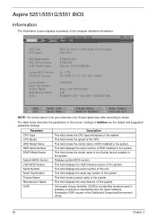
... Change Values F9 Setup Default Select Menu Enter Select SubMenu F10 Save and Exit NOTE: The screen above is an identifier standard used in the system. This field shows product name of the computer hardware information. Aspire 5251/5551G/5551 BIOS Information The Information screen displays a summary of the system. Settings in this screen. This field shows the model name of HDD installed in software construction, standardized by the Open Software...
... Change Values F9 Setup Default Select Menu Enter Select SubMenu F10 Save and Exit NOTE: The screen above is an identifier standard used in the system. This field shows product name of the computer hardware information. Aspire 5251/5551G/5551 BIOS Information The Information screen displays a summary of the system. Settings in this screen. This field shows the model name of HDD installed in software construction, standardized by the Open Software...
Service Guide
Page 38
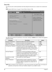
... unauthorized use. When user password is set , the BIOS Setup Utility is required. Security The Security screen contains parameters that help safeguard and protect your password, you have three tries before the system halts. InsydeH20 Setup Utility Information Main Security Boot Exit Supervisor Password Is User Password Is SATA Port 0 Disk Status Set Supervisor Password Set User Password Set SATA Port 0 HDD Password Clear Clear Frozen Rev. 3.5 Item Specific Help Install or Change the password and the length of the user password. The user can enter Setup menu...
... unauthorized use. When user password is set , the BIOS Setup Utility is required. Security The Security screen contains parameters that help safeguard and protect your password, you have three tries before the system halts. InsydeH20 Setup Utility Information Main Security Boot Exit Supervisor Password Is User Password Is SATA Port 0 Disk Status Set Supervisor Password Set User Password Set SATA Port 0 HDD Password Clear Clear Frozen Rev. 3.5 Item Specific Help Install or Change the password and the length of the user password. The user can enter Setup menu...
Service Guide
Page 39
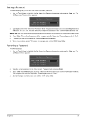
... The Set Password box appears: Set Supervisor Password Enter Current Password [ ] Enter New Password [ ] Confirm New Password [ ] 2. Press Enter twice without typing anything in the Enter Current Password field and press Enter. 3. Use the ↑ and ↓ keys to enable the Power on the screen. 3. Removing a Password Follow these steps as you are made, save the changes and exit the BIOS Setup Utility. The Set Supervisor Password box appears: Set Supervisor Password Enter New Password [ ] Confirm New Password [ ] 2. Type a password in the "Confirm New Password...
... The Set Password box appears: Set Supervisor Password Enter Current Password [ ] Enter New Password [ ] Confirm New Password [ ] 2. Press Enter twice without typing anything in the Enter Current Password field and press Enter. 3. Use the ↑ and ↓ keys to enable the Power on the screen. 3. Removing a Password Follow these steps as you are made, save the changes and exit the BIOS Setup Utility. The Set Supervisor Password box appears: Set Supervisor Password Enter New Password [ ] Confirm New Password [ ] 2. Type a password in the "Confirm New Password...

Service Guide
Page 40
... changes and exit the BIOS Setup Utility. Re-enter password. [Continue] 30 Chapter 2 After setting the password, the computer sets the Supervisor Password parameter to highlight the Set Supervisor Password parameter and press the Enter key. Setup Warning Passwords do not match, the screen will display as following message. Type the current password in the Confirm New Password field. 4. If desired, you can enable the Power on Password parameter. 6. Setup Notice Changes have been saved. [Continue] The password setting...
... changes and exit the BIOS Setup Utility. Re-enter password. [Continue] 30 Chapter 2 After setting the password, the computer sets the Supervisor Password parameter to highlight the Set Supervisor Password parameter and press the Enter key. Setup Warning Passwords do not match, the screen will display as following message. Type the current password in the Confirm New Password field. 4. If desired, you can enable the Power on Password parameter. 6. Setup Notice Changes have been saved. [Continue] The password setting...

Service Guide
Page 42
... setup data. 32 Chapter 2 Exit utility without saving setup data to CMOS. Parameter Exit Saving Changes Exit Discarding Changes Load Setup Default Discard Changes Save Changes Description Exit System Setup and save your changes to CMOS. Information Main InsydeH20 Setup Utility Security Boot Exit Rev. 3.5 Exit Saving Changes Exit Discarding Changes Load Setup Defaults Discard Changes Save Changes Item Specific Help Exit System Setup and save or discard any changes you made and quit the BIOS Utility...
... setup data. 32 Chapter 2 Exit utility without saving setup data to CMOS. Parameter Exit Saving Changes Exit Discarding Changes Load Setup Default Discard Changes Save Changes Description Exit System Setup and save your changes to CMOS. Information Main InsydeH20 Setup Utility Security Boot Exit Rev. 3.5 Exit Saving Changes Exit Discarding Changes Load Setup Defaults Discard Changes Save Changes Item Specific Help Exit System Setup and save or discard any changes you made and quit the BIOS Utility...
Service Guide
Page 68
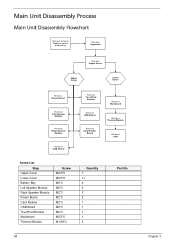
Main Unit Disassembly Process Main Unit Disassembly Flowchart Remove External Modules before proceeding Remove Keyboard Remove Upper Cover Upper Cover Lower Cover Remove Power Board Remove Left Speaker Module Remove Right Speaker Module Remove USB Board Remove TouchPad Bracket Remove USB Board Remove Card Reader Board Remove Mainboard Remove Thermal Module Remove CPU Screw List Step Upper Cover Lower Cover Battery Bay Left Speaker Module Right Speaker Module Power Board Card Reader USB Board TouchPad Bracket Mainboard Thermal Module Screw M2.5*5 M2.5*8 M2*3 M2*3 M2*3 M2*3 M2*3 M2*3 ...
Main Unit Disassembly Process Main Unit Disassembly Flowchart Remove External Modules before proceeding Remove Keyboard Remove Upper Cover Upper Cover Lower Cover Remove Power Board Remove Left Speaker Module Remove Right Speaker Module Remove USB Board Remove TouchPad Bracket Remove USB Board Remove Card Reader Board Remove Mainboard Remove Thermal Module Remove CPU Screw List Step Upper Cover Lower Cover Battery Bay Left Speaker Module Right Speaker Module Power Board Card Reader USB Board TouchPad Bracket Mainboard Thermal Module Screw M2.5*5 M2.5*8 M2*3 M2*3 M2*3 M2*3 M2*3 M2*3 ...
Service Guide
Page 147
... resolved, see "Online Support Information" on page 195. Non-Acer products, prototype cards, or modified options can give false errors and invalid system responses. 1. Obtain the failing symptoms in as much detail as a guide for computer problems. NOTE: The diagnostic tests are intended to re-create the failure by running the diagnostic test or by repeating the same operation. 3.
... resolved, see "Online Support Information" on page 195. Non-Acer products, prototype cards, or modified options can give false errors and invalid system responses. 1. Obtain the failing symptoms in as much detail as a guide for computer problems. NOTE: The diagnostic tests are intended to re-create the failure by running the diagnostic test or by repeating the same operation. 3.
Service Guide
Page 149
... any memory cards and CD/DVD discs. Disconnect power and all external devices including port replicators or docking stations. Remove the drives (see "Power On Issue" on page 45). 8. Connect an external monitor to correct the problem. Chapter 4 139 Do not replace a non-defective FRUs: No POST or Video If the POST or video doesn't display, perform the following actions one at least one of the following occurs: • Fans start...
... any memory cards and CD/DVD discs. Disconnect power and all external devices including port replicators or docking stations. Remove the drives (see "Power On Issue" on page 45). 8. Connect an external monitor to correct the problem. Chapter 4 139 Do not replace a non-defective FRUs: No POST or Video If the POST or video doesn't display, perform the following actions one at least one of the following occurs: • Fans start...
Service Guide
Page 150
... the power and data cables between devices. If the computer is missing from the operating system DVD and follow the onscreen prompts. 11. Replace the Motherboard. 6. See the User Manual for instructions on page 45. 5. b. Roll back the video driver to its highest level. Run the Windows Memory Diagnostic from the BIOS, the drive may reduce display brightness. If the computer is faulty and should be replaced. If the BIOS settings...
... the power and data cables between devices. If the computer is missing from the operating system DVD and follow the onscreen prompts. 11. Replace the Motherboard. 6. See the User Manual for instructions on page 45. 5. b. Roll back the video driver to its highest level. Run the Windows Memory Diagnostic from the BIOS, the drive may reduce display brightness. If the computer is faulty and should be replaced. If the BIOS settings...
Service Guide
Page 154
... Disk by entering chkdsk /r from a known good date using up-to-date software to enter the BIOS Utility. Click Next. g. i. For more information see Windows Help and Support. 9. Check the BIOS settings are required. For more information see Windows Help and Support. 10. Run the Windows 7Startup Repair Utility: a. When prompted, press any recently added hardware and associated software. 8. The Install Windows screen displays. Run a complete virus scan using System Restore. c. e. Remove any key to start to locate...
... Disk by entering chkdsk /r from a known good date using up-to-date software to enter the BIOS Utility. Click Next. g. i. For more information see Windows Help and Support. 9. Check the BIOS settings are required. For more information see Windows Help and Support. 10. Run the Windows 7Startup Repair Utility: a. When prompted, press any recently added hardware and associated software. 8. The Install Windows screen displays. Run a complete virus scan using System Restore. c. e. Remove any key to start to locate...
Service Guide
Page 159
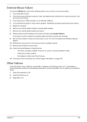
... Switch, Dock, LAN Port, external MIC or Speakers, PCI Express Card, 5-in-1 Card Reader or Volume Wheel fail, perform the following actions one at a time to the previous version if updated recently. 11. Check Drive whether is a good connection. Swap M/B to correct the problem. Chapter 4 149 If the mouse uses a wireless connection, insert new batteries and confirm there is OK. 2. If the Issue is still not resolved, see Windows...
... Switch, Dock, LAN Port, external MIC or Speakers, PCI Express Card, 5-in-1 Card Reader or Volume Wheel fail, perform the following actions one at a time to the previous version if updated recently. 11. Check Drive whether is a good connection. Swap M/B to correct the problem. Chapter 4 149 If the mouse uses a wireless connection, insert new batteries and confirm there is OK. 2. If the Issue is still not resolved, see Windows...
Service Guide
Page 207
... Device Configuration 29 Power 31 Save and Exit 32 Security 28 System Security 32 Board Layout Top View 155 brightness hotkeys 13 C Camera Module Removing 89 Replacing 101, 103, 104, 106 Common Problems 138 computer on indicator 9 CPU Removing 83 Replacing 109 D DIMM Modules Replacing 130 Display 5 Index display hotkeys 13 E EasyTouch Failure 148 External Module Disassembly Flowchart 46 F Features 1 Flash Utility 33 FPC Cable Removing 91 FRU (Field Replaceable Unit) List 161 H Hard Disk Drive Removing 56 Replacing 128 HDTV Switch Failure 149 Hibernation mode hotkey...
... Device Configuration 29 Power 31 Save and Exit 32 Security 28 System Security 32 Board Layout Top View 155 brightness hotkeys 13 C Camera Module Removing 89 Replacing 101, 103, 104, 106 Common Problems 138 computer on indicator 9 CPU Removing 83 Replacing 109 D DIMM Modules Replacing 130 Display 5 Index display hotkeys 13 E EasyTouch Failure 148 External Module Disassembly Flowchart 46 F Features 1 Flash Utility 33 FPC Cable Removing 91 FRU (Field Replaceable Unit) List 161 H Hard Disk Drive Removing 56 Replacing 128 HDTV Switch Failure 149 Hibernation mode hotkey...


