Quick Start Guide
Page 7
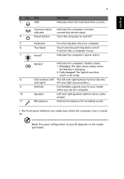
... and right mouse buttons. 9 Palmrest Comfortable support area for recording sound. 1. Battery1 Indicates the computer's battery status. 1. English 5 # Icon 3 Item HDD Description Indicates when the hard disk drive is active.
... and right mouse buttons. 9 Palmrest Comfortable support area for recording sound. 1. Battery1 Indicates the computer's battery status. 1. English 5 # Icon 3 Item HDD Description Indicates when the hard disk drive is active.
Service Guide
Page 7
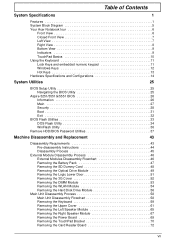
Table of Contents System Specifications 1 Features 1 System Block Diagram 5 Your Acer Notebook tour 6 Front View 6 Closed Front View 7 Left View 7 Right View...Hardware Specifications and Configurations 14 System Utilities 25 BIOS Setup Utility 25 Navigating the BIOS Utility 25 Aspire 5251/5551G/5551 BIOS 26 Information 26 Main 27 Security 28 Boot 31 Exit 32 BIOS Flash ...the 3G Cover 52 Removing the DIMM Module 53 Removing the WLAN Module 54 Removing the Hard Disk Drive Module 56 Main Unit Disassembly Process 58 Main Unit Disassembly Flowchart 58 Removing the Keyboard 59...
Table of Contents System Specifications 1 Features 1 System Block Diagram 5 Your Acer Notebook tour 6 Front View 6 Closed Front View 7 Left View 7 Right View...Hardware Specifications and Configurations 14 System Utilities 25 BIOS Setup Utility 25 Navigating the BIOS Utility 25 Aspire 5251/5551G/5551 BIOS 26 Information 26 Main 27 Security 28 Boot 31 Exit 32 BIOS Flash ...the 3G Cover 52 Removing the DIMM Module 53 Removing the WLAN Module 54 Removing the Hard Disk Drive Module 56 Main Unit Disassembly Process 58 Main Unit Disassembly Flowchart 58 Removing the Keyboard 59...
Service Guide
Page 8
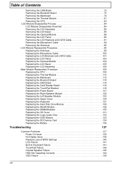
... Board 121 Replacing the Right Speaker Module 122 Replacing the Left Speaker Module 123 Replacing the Upper Cover 124 Replacing the Keyboard 127 Replacing the Hard Disk Drive Module 128 Replacing the WLAN Module 129 Replacing the DIMM Modules 130 Replacing the 3G Cover 131 Replacing the Logic Lower Door 132 Replacing...
... Board 121 Replacing the Right Speaker Module 122 Replacing the Left Speaker Module 123 Replacing the Upper Cover 124 Replacing the Keyboard 127 Replacing the Hard Disk Drive Module 128 Replacing the WLAN Module 129 Replacing the DIMM Modules 130 Replacing the 3G Cover 131 Replacing the Logic Lower Door 132 Replacing...
Service Guide
Page 12
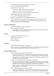
...; HDMI™ (High-Definition Multimedia Interface) with HDCP (High-bandwidth Digital Content Protection) support (Aspire 5251/5551/5551G) Storage Subsystem • 160/250/320/500/640 GB or larger hard disk drive • Multi-in-1 card reader, supporting: • Secure Digital™ (SD) Card, MultiMediaCard...Picture Card™ (xD) Audio Two built-in Acer 3DSonic™ stereo speakers High-definition audio support Built-in microphone MS-Sound compatible Storage • • 160/250/320/500/640 GB or larger hard disk drive Multi-in-1 card reader, supporting Secure Digital™...
...; HDMI™ (High-Definition Multimedia Interface) with HDCP (High-bandwidth Digital Content Protection) support (Aspire 5251/5551/5551G) Storage Subsystem • 160/250/320/500/640 GB or larger hard disk drive • Multi-in-1 card reader, supporting: • Secure Digital™ (SD) Card, MultiMediaCard...Picture Card™ (xD) Audio Two built-in Acer 3DSonic™ stereo speakers High-definition audio support Built-in microphone MS-Sound compatible Storage • • 160/250/320/500/640 GB or larger hard disk drive Multi-in-1 card reader, supporting Secure Digital™...
Service Guide
Page 16
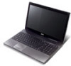
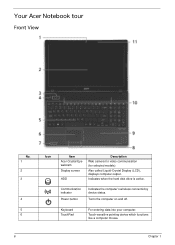
Indicates when the hard disk drive is active. Turns the computer on and off. Touch-sensitive pointing device which functions like a computer mouse. 6 Chapter 1 Your Acer Notebook tour Front View No. 1 2 3 4 5 6 Icon Item Acer Crystal Eye webcam Display screen HDD Description Web camera for video communication (for selected models). Communication indicator Power button Indicates the computer's wireless connectivitoy device status. Also called Liquid-Crystal Display (LCD), displays computer output. Keyboard TouchPad For entering data into your computer.
Indicates when the hard disk drive is active. Turns the computer on and off. Touch-sensitive pointing device which functions like a computer mouse. 6 Chapter 1 Your Acer Notebook tour Front View No. 1 2 3 4 5 6 Icon Item Acer Crystal Eye webcam Display screen HDD Description Web camera for video communication (for selected models). Communication indicator Power button Indicates the computer's wireless connectivitoy device status. Also called Liquid-Crystal Display (LCD), displays computer output. Keyboard TouchPad For entering data into your computer.
Service Guide
Page 19
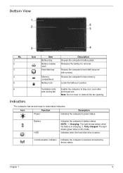
.... Fully charged: The light shows green when in position. 6 Ventilation slots Enable the computer to -read status indicators. Indicates when the hard disk drive is charging. 2. Chapter 1 9 Bottom View No. 1 2 3 4 5 Icon Item Battery bay Battery release latch Hard disk bay Memory compartment Battery lock Description Houses the computer's battery pack. Houses the computer...
.... Fully charged: The light shows green when in position. 6 Ventilation slots Enable the computer to -read status indicators. Indicates when the hard disk drive is charging. 2. Chapter 1 9 Bottom View No. 1 2 3 4 5 Icon Item Battery bay Battery release latch Hard disk bay Memory compartment Battery lock Description Houses the computer's battery pack. Houses the computer...
Service Guide
Page 28
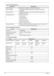
... ENE KB926 99-/100-/103-key keyboard Yes See "Hot Keys" on page 13. Hard Disk Drive Interface Item Vendor/model name Seagate Capacity (MB) 160, 250, 320, 500 Bytes per sector Data heads Drive Format Disks Spindle speed (RPM) Performance Specifications Buffer size Interface DC Power Requirements Voltage tolerance...(S3) Sleeping State (S4) Specification All devices in the system are turned off the whole system. Individual devices such as the CPU and hard disk may be power managed in this state. System Saves all system states and data onto disk prior to power off completely. CPU set ...
... ENE KB926 99-/100-/103-key keyboard Yes See "Hot Keys" on page 13. Hard Disk Drive Interface Item Vendor/model name Seagate Capacity (MB) 160, 250, 320, 500 Bytes per sector Data heads Drive Format Disks Spindle speed (RPM) Performance Specifications Buffer size Interface DC Power Requirements Voltage tolerance...(S3) Sleeping State (S4) Specification All devices in the system are turned off the whole system. Individual devices such as the CPU and hard disk may be power managed in this state. System Saves all system states and data onto disk prior to power off completely. CPU set ...
Service Guide
Page 41
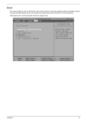
... Change Values F9 Setup Default Select Menu Enter Select SubMenu F10 Save and Exit Chapter 2 31 Bootable devices includes the USB diskette drives, the onboard hard disk drive and the DVD drive in the module bay. USB HDD : 5. InsydeH20 Setup Utility Information Main Security Boot Exit Rev. 3.5 Boot priority order: Item Specific Help 1. USB...
... Change Values F9 Setup Default Select Menu Enter Select SubMenu F10 Save and Exit Chapter 2 31 Bootable devices includes the USB diskette drives, the onboard hard disk drive and the DVD drive in the module bay. USB HDD : 5. InsydeH20 Setup Utility Information Main Security Boot Exit Rev. 3.5 Boot priority order: Item Specific Help 1. USB...
Service Guide
Page 66
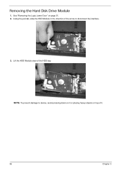
See "Removing the Logic Lower Door" on top of it. 56 Chapter 3 Lift the HDD Module clear of the arrow to device, avoid pressing down on it or placing heavy objects on page 51. 2. NOTE: To prevent damage to disconnect the interface. 3. Using the pull-tab, slide the HDD Module in the direction of the HDD bay. Removing the Hard Disk Drive Module 1.
See "Removing the Logic Lower Door" on top of it. 56 Chapter 3 Lift the HDD Module clear of the arrow to device, avoid pressing down on it or placing heavy objects on page 51. 2. NOTE: To prevent damage to disconnect the interface. 3. Using the pull-tab, slide the HDD Module in the direction of the HDD bay. Removing the Hard Disk Drive Module 1.
Service Guide
Page 138
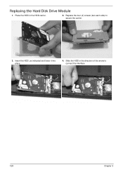
Place the HDD in the direction of the arrow to secure the carrier. 3. Replace the four (4) screws (two each side) to connect the interface. 128 Chapter 3 Slide the HDD in the HDD carrier. 2. Replacing the Hard Disk Drive Module 1. Insert the HDD, as indicated and lower it into place. 4.
Place the HDD in the direction of the arrow to secure the carrier. 3. Replace the four (4) screws (two each side) to connect the interface. 128 Chapter 3 Slide the HDD in the HDD carrier. 2. Replacing the Hard Disk Drive Module 1. Insert the HDD, as indicated and lower it into place. 4.
Service Guide
Page 160
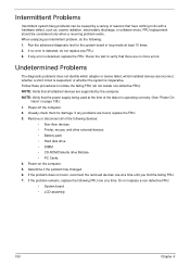
...). Power-off the computer. 2. Remove or disconnect all attached devices are no error is inoperative. If the problem remains, replace the following devices: • Non-Acer devices • Printer, mouse, and other external devices • Battery pack • Hard disk drive • DIMM • CD-ROM/Diskette...
...). Power-off the computer. 2. Remove or disconnect all attached devices are no error is inoperative. If the problem remains, replace the following devices: • Non-Acer devices • Printer, mouse, and other external devices • Battery pack • Hard disk drive • DIMM • CD-ROM/Diskette...
Service Guide
Page 207
... hotkeys 13 E EasyTouch Failure 148 External Module Disassembly Flowchart 46 F Features 1 Flash Utility 33 FPC Cable Removing 91 FRU (Field Replaceable Unit) List 161 H Hard Disk Drive Removing 56 Replacing 128 HDTV Switch Failure 149 Hibernation mode hotkey 13 Hot Keys 11 I Indicators 9 Intermittent Problems 150 Internal Microphone Failure 143 Internal Speaker...
... hotkeys 13 E EasyTouch Failure 148 External Module Disassembly Flowchart 46 F Features 1 Flash Utility 33 FPC Cable Removing 91 FRU (Field Replaceable Unit) List 161 H Hard Disk Drive Removing 56 Replacing 128 HDTV Switch Failure 149 Hibernation mode hotkey 13 Hot Keys 11 I Indicators 9 Intermittent Problems 150 Internal Microphone Failure 143 Internal Speaker...


