Quick Start Guide
Page 7
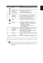
Battery1 Indicates the computer's battery status. 1. Communication indicator Indicates the computer's wireless connectivity device status. 4 Power button Turns the computer on the model purchased. Fully charged: The light shows blue when in AC mode. 8 Click buttons (left The left and right ... your computer. 6 Touchpad Touch-sensitive pointing device which functions like the and right) left and right buttons function like a computer mouse. 7 Power1 Indicates the computer's power status. Charging: The light shows amber when the battery is charging. 2.
Battery1 Indicates the computer's battery status. 1. Communication indicator Indicates the computer's wireless connectivity device status. 4 Power button Turns the computer on the model purchased. Fully charged: The light shows blue when in AC mode. 8 Click buttons (left The left and right ... your computer. 6 Touchpad Touch-sensitive pointing device which functions like the and right) left and right buttons function like a computer mouse. 7 Power1 Indicates the computer's power status. Charging: The light shows amber when the battery is charging. 2.
Quick Start Guide
Page 8
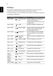
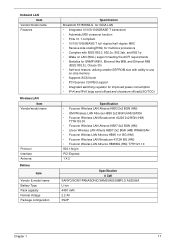
... Touchpad toggle Speaker toggle Switches display output between the display screen, external monitor (if connected) and both. Turns the speakers on and off to save power. Play/Pause Play or pause a selected media file. Press any key to the next media file. Hotkey + + Icon Function Description Communication Enables / disables the computer...
... Touchpad toggle Speaker toggle Switches display output between the display screen, external monitor (if connected) and both. Turns the speakers on and off to save power. Play/Pause Play or pause a selected media file. Press any key to the next media file. Hotkey + + Icon Function Description Communication Enables / disables the computer...
Service Guide
Page 7
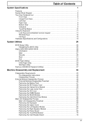
Table of Contents System Specifications 1 Features 1 System Block Diagram 5 Your Acer Notebook tour 6 Front View 6 Closed Front View 7 Left View 7 Right View 8 Bottom View 9 ...Keys 13 Hardware Specifications and Configurations 14 System Utilities 25 BIOS Setup Utility 25 Navigating the BIOS Utility 25 Aspire 5251/5551G/5551 BIOS 26 Information 26 Main 27 Security 28 Boot 31 Exit 32 BIOS Flash Utilities 33 DOS... Left Speaker Module 65 Removing the Right Speaker Module 67 Removing the Power Board 69 Removing the TouchPad Bracket 70 Removing the Card Reader Board 72 VII
Table of Contents System Specifications 1 Features 1 System Block Diagram 5 Your Acer Notebook tour 6 Front View 6 Closed Front View 7 Left View 7 Right View 8 Bottom View 9 ...Keys 13 Hardware Specifications and Configurations 14 System Utilities 25 BIOS Setup Utility 25 Navigating the BIOS Utility 25 Aspire 5251/5551G/5551 BIOS 26 Information 26 Main 27 Security 28 Boot 31 Exit 32 BIOS Flash Utilities 33 DOS... Left Speaker Module 65 Removing the Right Speaker Module 67 Removing the Power Board 69 Removing the TouchPad Bracket 70 Removing the Card Reader Board 72 VII
Service Guide
Page 8
... Replacing the Bluetooth Board 115 Replacing the USB Board 116 Replacing the Card Reader Board 118 Replacing the TouchPad Bracket 119 Replacing the Power Board 121 Replacing the Right Speaker Module 122 Replacing the Left Speaker Module 123 Replacing the Upper Cover 124 Replacing the Keyboard 127 ... Lower Door 132 Replacing the ODD Module 133 Replacing the SD Dummy Card 134 Replacing the Battery 135 Troubleshooting 137 Common Problems 137 Power On Issue 138 No Display Issue 139 Random Loss of BIOS Settings 140 LCD Failure 141 Built-In Keyboard Failure 141 TouchPad Failure ...
... Replacing the Bluetooth Board 115 Replacing the USB Board 116 Replacing the Card Reader Board 118 Replacing the TouchPad Bracket 119 Replacing the Power Board 121 Replacing the Right Speaker Module 122 Replacing the Left Speaker Module 123 Replacing the Upper Cover 124 Replacing the Keyboard 127 ... Lower Door 132 Replacing the ODD Module 133 Replacing the SD Dummy Card 134 Replacing the Battery 135 Troubleshooting 137 Common Problems 137 Power On Issue 138 No Display Issue 139 Random Loss of BIOS Settings 140 LCD Failure 141 Built-In Keyboard Failure 141 TouchPad Failure ...
Service Guide
Page 9
...View 156 USB/B Board 157 Power Board 157 CR/B Board 158 Clearing Password Check and BIOS Recovery 159 Clearing Password Check 159 Clear CMOS Jumper 159 BIOS Recovery by Crisis Disk 160 FRU (Field Replaceable Unit) List 161 Aspire 5251/5551G/5551 Exploded Diagrams 162... Main Assembly 162 Base Assembly 163 LED Assembly 164 Aspire 5251/5551G/5551 FRU List 165 Screw List 166 Model Definition and Configuration 168 Aspire 5251 168 Aspire 5551G 170 Aspire 5551 179 Test Compatible Components 187 ...
...View 156 USB/B Board 157 Power Board 157 CR/B Board 158 Clearing Password Check and BIOS Recovery 159 Clearing Password Check 159 Clear CMOS Jumper 159 BIOS Recovery by Crisis Disk 160 FRU (Field Replaceable Unit) List 161 Aspire 5251/5551G/5551 Exploded Diagrams 162... Main Assembly 162 Base Assembly 163 LED Assembly 164 Aspire 5251/5551G/5551 FRU List 165 Screw List 166 Model Definition and Configuration 168 Aspire 5251 168 Aspire 5551G 170 Aspire 5551 179 Test Compatible Components 187 ...
Service Guide
Page 13
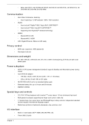
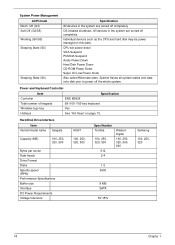
... DVD+RW, 5X DVD-RAM Communication • Acer Video Conference, featuring: • Acer Crystal Eye 1.3 MP webcam, 1280 x 1024 resolution • WLAN: • Acer InviLink™ Nplify™ 802.11b/g/n Wi-Fi CERTIFIED™ • Acer InviLink™ 802.11b/g Wi-Fi CERTIFIED™... 381 (W) x 253 (D) x 25/34 (H) mm (15 x 9.9 x 0.98/1.3 inches)2.6 kg (5.74 lbs.)10 with 6-cell battery pack Power subsystem • ACPI 3.0 CPU power management standard: supports Standby and Hibernation power-saving modes • 3-pin 65 W AC adapter: • 108 (W) x 46 (D) x 29.5 (H) mm (4.25 x 1.81 x ...
... DVD+RW, 5X DVD-RAM Communication • Acer Video Conference, featuring: • Acer Crystal Eye 1.3 MP webcam, 1280 x 1024 resolution • WLAN: • Acer InviLink™ Nplify™ 802.11b/g/n Wi-Fi CERTIFIED™ • Acer InviLink™ 802.11b/g Wi-Fi CERTIFIED™... 381 (W) x 253 (D) x 25/34 (H) mm (15 x 9.9 x 0.98/1.3 inches)2.6 kg (5.74 lbs.)10 with 6-cell battery pack Power subsystem • ACPI 3.0 CPU power management standard: supports Standby and Hibernation power-saving modes • 3-pin 65 W AC adapter: • 108 (W) x 46 (D) x 29.5 (H) mm (4.25 x 1.81 x ...
Service Guide
Page 16
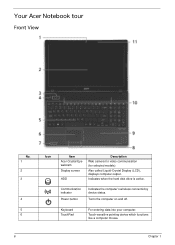
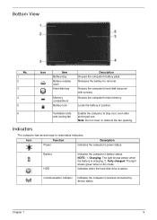
Keyboard TouchPad For entering data into your computer. Turns the computer on and off. Also called Liquid-Crystal Display (LCD), displays computer output. Your Acer Notebook tour Front View No. 1 2 3 4 5 6 Icon Item Acer Crystal Eye webcam Display screen HDD Description Web camera for video communication (for selected models). Touch-sensitive pointing device which functions like a computer mouse. 6 Chapter 1 Communication indicator Power button Indicates the computer's wireless connectivitoy device status. Indicates when the hard disk drive is active.
Keyboard TouchPad For entering data into your computer. Turns the computer on and off. Also called Liquid-Crystal Display (LCD), displays computer output. Your Acer Notebook tour Front View No. 1 2 3 4 5 6 Icon Item Acer Crystal Eye webcam Display screen HDD Description Web camera for video communication (for selected models). Touch-sensitive pointing device which functions like a computer mouse. 6 Chapter 1 Communication indicator Power button Indicates the computer's wireless connectivitoy device status. Indicates when the hard disk drive is active.

Service Guide
Page 17
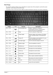
... audio output. Connects to HDMI devices 7 Connect to an Ethernet 10/100/1000-based network. No. 7 8 9 10 11 Icon Item Power1 Description Indicates the computer's power status. NOTE: Push to a display device (e.g. Connects to remove/install the card. Closed Front View No. 1 Left View Icon Item Multi-in AC mode. Charging...
... audio output. Connects to HDMI devices 7 Connect to an Ethernet 10/100/1000-based network. No. 7 8 9 10 11 Icon Item Power1 Description Indicates the computer's power status. NOTE: Push to a display device (e.g. Connects to remove/install the card. Closed Front View No. 1 Left View Icon Item Multi-in AC mode. Charging...
Service Guide
Page 19
... prolonged use. Communication indicator Indicates the computer's wireless connectivitoy device status. Note: Do not cover or obstruct the fan opening. NOTE: 1. Icon Function Power Description Indicates the computer's power status. Locks the battery in AC mode. Chapter 1 9 Battery HDD Indicates the computer's battery status. Fully charged: The light shows green when in...
... prolonged use. Communication indicator Indicates the computer's wireless connectivitoy device status. Note: Do not cover or obstruct the fan opening. NOTE: 1. Icon Function Power Description Indicates the computer's power status. Locks the battery in AC mode. Chapter 1 9 Battery HDD Indicates the computer's battery status. Fully charged: The light shows green when in...
Service Guide
Page 23
... Turns the internal touchpad on and off. Turns the speakers on and off to the next media file. Increases the screen brightness. Jump to save power. Play or pause a selected media file. Turns the display screen backlight off . Switches display output between the display screen, external monitor (if connected) and both...
... Turns the internal touchpad on and off. Turns the speakers on and off to the next media file. Increases the screen brightness. Jump to save power. Play or pause a selected media file. Turns the display screen backlight off . Switches display output between the display screen, external monitor (if connected) and both...
Service Guide
Page 27
... smaller EEPROM size with ability to use on-chip memory • Supports iSCSI boott • PCI Express CLKREQ support • Integrated switching regulator for improved power consumption • IPv4 and IPv6 large send offload and checksum offload(LSO/TCO) Specification • Foxconn Wireless LAN Atheros HB93 2x2 BGN (HM) • QMI...
... smaller EEPROM size with ability to use on-chip memory • Supports iSCSI boott • PCI Express CLKREQ support • Integrated switching regulator for improved power consumption • IPv4 and IPv6 large send offload and checksum offload(LSO/TCO) Specification • Foxconn Wireless LAN Atheros HB93 2x2 BGN (HM) • QMI...
Service Guide
Page 28
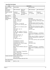
... system states and data onto disk prior to power off completely. CPU set power down VGA Suspend PCMCIA Suspend Audio Power Down Hard Disk Power Down CD-ROM Power Down Super I/O Low Power mode Also called Hibernate state. Power and Keyboard Controller Item Specification Controller Total number ...(MB) 160, 250, 320, 500 Bytes per sector Data heads Drive Format Disks Spindle speed (RPM) Performance Specifications Buffer size Interface DC Power Requirements Voltage tolerance HGST 160, 250, 320, 500 Specification Toshiba 160, 250, 320, 500 512 2-4 Western Digital 160, 250, 320, ...
... system states and data onto disk prior to power off completely. CPU set power down VGA Suspend PCMCIA Suspend Audio Power Down Hard Disk Power Down CD-ROM Power Down Super I/O Low Power mode Also called Hibernate state. Power and Keyboard Controller Item Specification Controller Total number ...(MB) 160, 250, 320, 500 Bytes per sector Data heads Drive Format Disks Spindle speed (RPM) Performance Specifications Buffer size Interface DC Power Requirements Voltage tolerance HGST 160, 250, 320, 500 Specification Toshiba 160, 250, 320, 500 512 2-4 Western Digital 160, 250, 320, ...
Service Guide
Page 29
...-1, CD-ROM/XA Mode-2 Form-1 and Mode-2 Form-2, CD-i, VideoCD, CD-Text Loading mechanism Drawer (Solenoid Open) Tact SW (Open) Emergency Release (draw open hole) Power Requirement Input Voltage DC 5 V +/- 5% Chapter 1 19 CD Read: CD-DA, CD-ROM Mode-1, CD-ROM/XA Mode-2 Form-1 and Mode-2 Form-2, CD-i, CD-i Bridge, Video...
...-1, CD-ROM/XA Mode-2 Form-1 and Mode-2 Form-2, CD-i, VideoCD, CD-Text Loading mechanism Drawer (Solenoid Open) Tact SW (Open) Emergency Release (draw open hole) Power Requirement Input Voltage DC 5 V +/- 5% Chapter 1 19 CD Read: CD-DA, CD-ROM Mode-1, CD-ROM/XA Mode-2 Form-1 and Mode-2 Form-2, CD-i, CD-i Bridge, Video...
Service Guide
Page 32
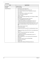
... 5-in-1 card reader • Push-push type, with dummy card • Built-in 250mA Power MOS for memory card • Over Current Protection and Over Temperature Protection • Power saving • Power Down when no memory card is inserted • Power Idle (Selective Suspend) • USB2.0 Interface • Support both High-Speed (480 Mbps...
... 5-in-1 card reader • Push-push type, with dummy card • Built-in 250mA Power MOS for memory card • Over Current Protection and Over Temperature Protection • Power saving • Power Down when no memory card is inserted • Power Idle (Selective Suspend) • USB2.0 Interface • Support both High-Speed (480 Mbps...
Service Guide
Page 33
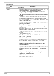
... digital BEEP generator • Headphone amplifier on port-I (HP-OUT) is designed to drive output without external DC blocking capacitors • Supports EAPD (External Amplifier Power Down) control for external amplifier • 48-pin LQFP 'Green' package • WaveRT-based audio function driver for Windows Vista • EAX™ 1.0 & 2.0 compatible •... (AEC), Noise Suppression (NS), and Beam Forming(BF)technology for voice application • Smart multiple streaming operation • HDMI audio driver for AMD platform • Acer exclusive software features Chapter 1 23
... digital BEEP generator • Headphone amplifier on port-I (HP-OUT) is designed to drive output without external DC blocking capacitors • Supports EAPD (External Amplifier Power Down) control for external amplifier • 48-pin LQFP 'Green' package • WaveRT-based audio function driver for Windows Vista • EAX™ 1.0 & 2.0 compatible •... (AEC), Noise Suppression (NS), and Beam Forming(BF)technology for voice application • Smart multiple streaming operation • HDMI audio driver for AMD platform • Acer exclusive software features Chapter 1 23
Service Guide
Page 38
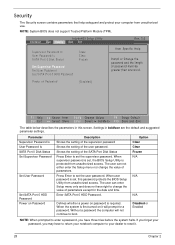
... and time. If you forget your password, you have right to change the value of password must be greater than one word. Power on Password [Disabled] F1 Help ESC Exit Select Item F5/F6 Change Values F9 Setup Default Select Menu Enter Select SubMenu F10 Save...Security The Security screen contains parameters that help safeguard and protect your computer from unauthorized access. When user password is required. Defines whether a power on password is set , the BIOS Setup Utility is first turned on Password Description Shows the setting of the supervisor password Shows the setting ...
... and time. If you forget your password, you have right to change the value of password must be greater than one word. Power on Password [Disabled] F1 Help ESC Exit Select Item F5/F6 Change Values F9 Setup Default Select Menu Enter Select SubMenu F10 Save...Security The Security screen contains parameters that help safeguard and protect your computer from unauthorized access. When user password is required. Defines whether a power on password is set , the BIOS Setup Utility is first turned on Password Description Shows the setting of the supervisor password Shows the setting ...
Service Guide
Page 39
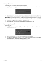
... save and exit the BIOS Setup Utility. Use the ↑ and ↓ keys to "Clear". 4. After all changes are done, press F10 to enable the Power on the screen. 3. Press Enter. Type the current password in the "Confirm New Password" field. Setting a Password Follow these steps: 1. The Set Supervisor Password box...
... save and exit the BIOS Setup Utility. Use the ↑ and ↓ keys to "Clear". 4. After all changes are done, press F10 to enable the Power on the screen. 3. Press Enter. Type the current password in the "Confirm New Password" field. Setting a Password Follow these steps: 1. The Set Supervisor Password box...

Service Guide
Page 40
... following . If the current password entered does not match the actual current password, the screen will display as following message. When you can enable the Power on Password parameter. 6. Setup Warning Invalid Password. [Continue] If the new password and confirm new password strings do not match. After setting the password, the...
... following . If the current password entered does not match the actual current password, the screen will display as following message. When you can enable the Power on Password parameter. 6. Setup Warning Invalid Password. [Continue] If the new password and confirm new password strings do not match. After setting the password, the...
Service Guide
Page 43
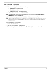
...should create a Crisis Recovery Diskette before you run the Flash. 1. The Flash utility has auto-execution function. NOTE: Please use the AC adaptor power supply when you use the Flash. Follow the steps below to the bootable diskette. 3. Copy the Flash utilities to run the Flash utility. Chapter ...2 33 If the battery pack does not contain enough power to update the system BIOS Flash ROM. Then boot the system from the bootable diskette. Prepare a bootable diskette. 2. NOTE: Do not install ...
...should create a Crisis Recovery Diskette before you run the Flash. 1. The Flash utility has auto-execution function. NOTE: Please use the AC adaptor power supply when you use the Flash. Follow the steps below to the bootable diskette. 3. Copy the Flash utilities to run the Flash utility. Chapter ...2 33 If the battery pack does not contain enough power to update the system BIOS Flash ROM. Then boot the system from the bootable diskette. Prepare a bootable diskette. 2. NOTE: Do not install ...
Service Guide
Page 45
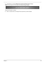
Plug in the AC power to continue. 5. Flash is not connected, the following message displays. 4. Chapter 2 35 NOTE: If the AC power is complete when the message Flash programming complete displays. In flash BIOS, the message Please do not remove AC Power Source displays.
Plug in the AC power to continue. 5. Flash is not connected, the following message displays. 4. Chapter 2 35 NOTE: If the AC power is complete when the message Flash programming complete displays. In flash BIOS, the message Please do not remove AC Power Source displays.


