Service Guide
Page 7
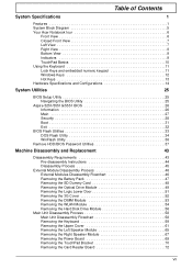
Table of Contents System Specifications 1 Features 1 System Block Diagram 5 Your Acer Notebook tour 6 Front View 6 Closed Front View 7 Left View 7 Right View 8 Bottom View 9 Indicators 9 TouchPad Basics 10 Using the Keyboard ...25 Aspire 5251/5551G/5551 BIOS 26 Information 26 Main 27 Security 28 Boot 31 Exit 32 BIOS Flash Utilities 33 DOS Flash Utility 34 WinFlash Utility 36 Remove HDD/BIOS Password Utilities 37 Machine Disassembly and Replacement 43 Disassembly Requirements 43 Pre-disassembly Instructions 44 Disassembly Process 45 External Module Disassembly Process...
Table of Contents System Specifications 1 Features 1 System Block Diagram 5 Your Acer Notebook tour 6 Front View 6 Closed Front View 7 Left View 7 Right View 8 Bottom View 9 Indicators 9 TouchPad Basics 10 Using the Keyboard ...25 Aspire 5251/5551G/5551 BIOS 26 Information 26 Main 27 Security 28 Boot 31 Exit 32 BIOS Flash Utilities 33 DOS Flash Utility 34 WinFlash Utility 36 Remove HDD/BIOS Password Utilities 37 Machine Disassembly and Replacement 43 Disassembly Requirements 43 Pre-disassembly Instructions 44 Disassembly Process 45 External Module Disassembly Process...
Service Guide
Page 8
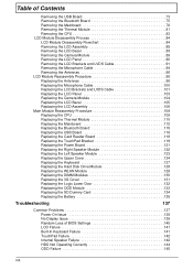
... USB Board 73 Removing the Bluetooth Board 75 Removing the Mainboard 76 Removing the Thermal Module 81 Removing the CPU 83 LCD Module Disassembly Process 84 LCD Module Disassembly Flowchart 84 Removing the LCD Assembly 85 Removing the LCD Bezel 88 Removing the Camera Module 89 Removing the LCD Panel 90 Removing...
... USB Board 73 Removing the Bluetooth Board 75 Removing the Mainboard 76 Removing the Thermal Module 81 Removing the CPU 83 LCD Module Disassembly Process 84 LCD Module Disassembly Flowchart 84 Removing the LCD Assembly 85 Removing the LCD Bezel 88 Removing the Camera Module 89 Removing the LCD Panel 90 Removing...
Service Guide
Page 53
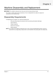
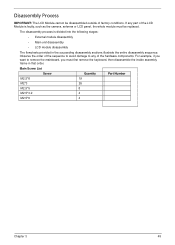
... outside housing and color may vary from the mass produced model. Chapter 3 43 During the disassembly process, group the screws with the corresponding components to disassemble the notebook computer for the different components vary in size. This chapter contains step-by-step ...procedures on how to avoid mismatch when putting back the components. Disassembly Requirements To disassemble the computer, you need the following tools: • Wrist grounding strap and conductive mat for preventing electrostatic discharge •...
... outside housing and color may vary from the mass produced model. Chapter 3 43 During the disassembly process, group the screws with the corresponding components to disassemble the notebook computer for the different components vary in size. This chapter contains step-by-step ...procedures on how to avoid mismatch when putting back the components. Disassembly Requirements To disassemble the computer, you need the following tools: • Wrist grounding strap and conductive mat for preventing electrostatic discharge •...
Service Guide
Page 54
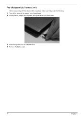
Remove the battery pack. 44 Chapter 3 Place the system on a flat, stable surface. 4. Turn off the power to the system and all power and signal cables from the system. 3. Pre-disassembly Instructions Before proceeding with the disassembly procedure, make sure that you do the following: 1. Unplug the AC adapter and all peripherals. 2.
Remove the battery pack. 44 Chapter 3 Place the system on a flat, stable surface. 4. Turn off the power to the system and all power and signal cables from the system. 3. Pre-disassembly Instructions Before proceeding with the disassembly procedure, make sure that you do the following: 1. Unplug the AC adapter and all peripherals. 2.
Service Guide
Page 55
..., you want to any part of the LCD Module is divided into the following stages: • External module disassembly • Main unit disassembly • LCD module disassembly The flowcharts provided in that order. The disassembly process is faulty, such as the camera, antenna or LCD panel, the whole module must first remove the keyboard...
..., you want to any part of the LCD Module is divided into the following stages: • External module disassembly • Main unit disassembly • LCD module disassembly The flowcharts provided in that order. The disassembly process is faulty, such as the camera, antenna or LCD panel, the whole module must first remove the keyboard...
Service Guide
Page 56
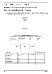
...the switch board. Turn off system and peripherals power Disconnect power and signal cables from the mass produced model. External Module Disassembly Process IMPORTANT: The outside housing and color may vary from system Remove Battery Remove Dummy Card Remove HDD/WLAN/DIM M Door... M2*3 M2*3 M2.5*8 M2*3 M3*3 Quantity 1 2 1 2 1 4 Part No. 46 Chapter 3 External Modules Disassembly Flowchart The flowchart below gives you a graphic representation of the external module disassembly sequence and instructs you on the components that need to remove the keyboard, you want to be removed during...
...the switch board. Turn off system and peripherals power Disconnect power and signal cables from the mass produced model. External Module Disassembly Process IMPORTANT: The outside housing and color may vary from system Remove Battery Remove Dummy Card Remove HDD/WLAN/DIM M Door... M2*3 M2*3 M2.5*8 M2*3 M3*3 Quantity 1 2 1 2 1 4 Part No. 46 Chapter 3 External Modules Disassembly Flowchart The flowchart below gives you a graphic representation of the external module disassembly sequence and instructs you on the components that need to remove the keyboard, you want to be removed during...
Service Guide
Page 68
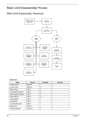
Main Unit Disassembly Process Main Unit Disassembly Flowchart Remove External Modules before proceeding Remove Keyboard Remove Upper Cover Upper Cover Lower Cover Remove Power Board Remove Left Speaker Module Remove Right Speaker ...
Main Unit Disassembly Process Main Unit Disassembly Flowchart Remove External Modules before proceeding Remove Keyboard Remove Upper Cover Upper Cover Lower Cover Remove Power Board Remove Left Speaker Module Remove Right Speaker ...
Service Guide
Page 71
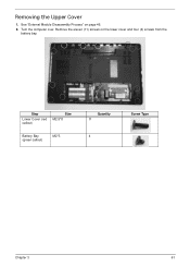
Remove the eleven (11) screws on page 46. 2. Step Lower Cover (red callout) Size M2.5*8 Battery Bay (green callout) M2*3 Quantity 11 4 Screw Type Chapter 3 61 Removing the Upper Cover 1. See "External Module Disassembly Process" on the lower cover and four (4) screws from the battery bay. Turn the computer over.
Remove the eleven (11) screws on page 46. 2. Step Lower Cover (red callout) Size M2.5*8 Battery Bay (green callout) M2*3 Quantity 11 4 Screw Type Chapter 3 61 Removing the Upper Cover 1. See "External Module Disassembly Process" on the lower cover and four (4) screws from the battery bay. Turn the computer over.
Service Guide
Page 94
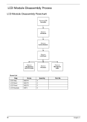
LCD Module Disassembly Process LCD Module Disassembly Flowchart Remove LCD Assembly Remove LCD Bezel Remove Camera Module Remove LCD Panel Remove LCD Brackets and FPC Cable Remove Antennas Screw List Step LCD Assy LCD Bezel LCD Panel LCD Brackets Screw M2.5*5 M2.5*6 M2.5*5 M2*3 Quantity 4 2 2 6 Remove Microphone Cable Part No. 84 Chapter 3
LCD Module Disassembly Process LCD Module Disassembly Flowchart Remove LCD Assembly Remove LCD Bezel Remove Camera Module Remove LCD Panel Remove LCD Brackets and FPC Cable Remove Antennas Screw List Step LCD Assy LCD Bezel LCD Panel LCD Brackets Screw M2.5*5 M2.5*6 M2.5*5 M2*3 Quantity 4 2 2 6 Remove Microphone Cable Part No. 84 Chapter 3
Service Guide
Page 149
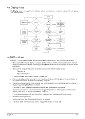
... at least one of the following actions one until the failure point is selected. If the POST or video appears on the external display, see "Disassembly Process" on page 195. Restart the computer. Reseat the memory modules. 7. If the Issue is no power, see "Online Support Information" on page 45...
... at least one of the following actions one until the failure point is selected. If the POST or video appears on the external display, see "Disassembly Process" on page 195. Restart the computer. Reseat the memory modules. 7. If the Issue is no power, see "Online Support Information" on page 45...
Service Guide
Page 150
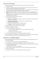
...level. Remove and reinstall the video driver. 8. If the BIOS settings are no device conflicts. • No hardware is virus free. 3. See "Disassembly Process" on page 45. 3. Random Loss of BIOS information, perform the following actions one at a time to the previous version if updated. 7....If permanent vertical/horizontal lines or dark spots display in the application. c. If the Issue is faulty and should be replaced. d. See "Disassembly Process" on page 45. 5. Run the Windows Memory Diagnostic from the BIOS, the drive may reduce display brightness. If the Issue is ...
...level. Remove and reinstall the video driver. 8. If the BIOS settings are no device conflicts. • No hardware is virus free. 3. See "Disassembly Process" on page 45. 3. Random Loss of BIOS information, perform the following actions one at a time to the previous version if updated. 7....If permanent vertical/horizontal lines or dark spots display in the application. c. If the Issue is faulty and should be replaced. d. See "Disassembly Process" on page 45. 5. Run the Windows Memory Diagnostic from the BIOS, the drive may reduce display brightness. If the Issue is ...
Service Guide
Page 154
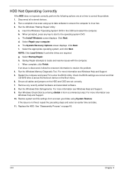
.... 2. For more information see Windows Help and Support. 5. If the issue is virus free. 3. Select Repair your computer. Run the Windows Memory Diagnostic Tool. See "Disassembly Process" on the Boot menu. 6. HDD Not Operating Correctly If the HDD does not operate correctly, perform the following actions one at a time to enter...
.... 2. For more information see Windows Help and Support. 5. If the issue is virus free. 3. Select Repair your computer. Run the Windows Memory Diagnostic Tool. See "Disassembly Process" on the Boot menu. 6. HDD Not Operating Correctly If the HDD does not operate correctly, perform the following actions one at a time to enter...
Service Guide
Page 157
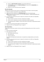
...the drive is identical to the ODD. Check for broken connectors on page 14. 3. Try an alternate cable, if available. e. See "Disassembly Process" on page 45. b. Try an alternate cable, if available. If the drive works with the new cable, the original cable ...Reseat the drive ensuring and all cables are connected correctly. 5. Test the drive using other ATA Devices shown if applicable. Replace the ODD. See "Disassembly Process" on page 45. If the drive works with alternate discs, the original disc is checked and click OK. d. Play a DVD movie f. ...
...the drive is identical to the ODD. Check for broken connectors on page 14. 3. Try an alternate cable, if available. e. See "Disassembly Process" on page 45. b. Try an alternate cable, if available. If the drive works with the new cable, the original cable ...Reseat the drive ensuring and all cables are connected correctly. 5. Test the drive using other ATA Devices shown if applicable. Replace the ODD. See "Disassembly Process" on page 45. If the drive works with alternate discs, the original disc is checked and click OK. d. Play a DVD movie f. ...
Service Guide
Page 207
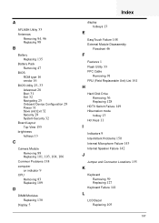
... Common Problems 138 computer on indicator 9 CPU Removing 83 Replacing 109 D DIMM Modules Replacing 130 Display 5 Index display hotkeys 13 E EasyTouch Failure 148 External Module Disassembly Flowchart 46 F Features 1 Flash Utility 33 FPC Cable Removing 91 FRU (Field Replaceable Unit) List 161 H Hard Disk Drive Removing 56 Replacing 128 HDTV Switch...
... Common Problems 138 computer on indicator 9 CPU Removing 83 Replacing 109 D DIMM Modules Replacing 130 Display 5 Index display hotkeys 13 E EasyTouch Failure 148 External Module Disassembly Flowchart 46 F Features 1 Flash Utility 33 FPC Cable Removing 91 FRU (Field Replaceable Unit) List 161 H Hard Disk Drive Removing 56 Replacing 128 HDTV Switch...
Service Guide
Page 208
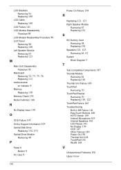
... 84 LCD Module Reassembly Procedure 98 LCD Panel Removing 90 Replacing 100 Left Speaker Module Removing 65 Replacing 123 M Main Unit Disassembly Flowchart 58 Mainboard Removing 72, 73, 75, 76 Replacing 112 media access on indicator 9 Memory Replacing 130 Memory Check 138 Model Definition 168 N No Display ...
... 84 LCD Module Reassembly Procedure 98 LCD Panel Removing 90 Replacing 100 Left Speaker Module Removing 65 Replacing 123 M Main Unit Disassembly Flowchart 58 Mainboard Removing 72, 73, 75, 76 Replacing 112 media access on indicator 9 Memory Replacing 130 Memory Check 138 Model Definition 168 N No Display ...


