
English Manual
Page 2
... ICON HEALTH & FITNESS, INC., 1500 S. 1000 W., LOGAN, UT 84321-9813 2 You may not apply to the original purchaser. WEIDER is authorized by ICON. ICON's obligation under normal use , costs of removal, installation or other rights which warranty claim is limited in... IDENTIFICATION CHART before beginning assembly. Table of Contents LIMITED WARRANTY 2 IMPORTANT PRECAUTIONS 3 BEFORE YOU BEGIN 4 ASSEMBLY 5 ADJUSTMENT 16 WEIGHT RESISTANCE CHART 17 TROUBLE-SHOOTING AND MAINTENANCE 18 CABLE DIAGRAM 19 ORDERING REPLACEMENT PARTS Back Cover Note: An EXPLODED DRAWING/PART LIST ...
... ICON HEALTH & FITNESS, INC., 1500 S. 1000 W., LOGAN, UT 84321-9813 2 You may not apply to the original purchaser. WEIDER is authorized by ICON. ICON's obligation under normal use , costs of removal, installation or other rights which warranty claim is limited in... IDENTIFICATION CHART before beginning assembly. Table of Contents LIMITED WARRANTY 2 IMPORTANT PRECAUTIONS 3 BEFORE YOU BEGIN 4 ASSEMBLY 5 ADJUSTMENT 16 WEIGHT RESISTANCE CHART 17 TROUBLE-SHOOTING AND MAINTENANCE 18 CABLE DIAGRAM 19 ORDERING REPLACEMENT PARTS Back Cover Note: An EXPLODED DRAWING/PART LIST ...
English Manual
Page 3
...wear athletic shoes for protection. 5. Never release the press arm, butterfly arms, leg lever, lat bar, leg press plate, or nylon strap while weights are adequately informed of all of this product. 3 Cover the floor or carpet beneath the home gym system for foot protection. 10. Replace any...to ensure that the cables remain on all precautions. 2. Make sure that all instructions before using . Inspect and tighten all times. The weights will fall with pre-existing health problems. Read all users of the home gym system are raised. Keep hands and feet away from the...
...wear athletic shoes for protection. 5. Never release the press arm, butterfly arms, leg lever, lat bar, leg press plate, or nylon strap while weights are adequately informed of all of this product. 3 Cover the floor or carpet beneath the home gym system for foot protection. 10. Replace any...to ensure that the cables remain on all precautions. 2. Make sure that all instructions before using . Inspect and tighten all times. The weights will fall with pre-existing health problems. Read all users of the home gym system are raised. Keep hands and feet away from the...
English Manual
Page 4
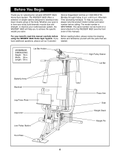
... want. The serial number can be found on a decal attached to achieve the specific results you to the WEIDER¨ 8620 (see the front cover of the body. The WEIDER¨ 8620 offers a selection of weight stations designed to develop every major muscle group of this manual carefully before calling. Service Department toll-free at...
... want. The serial number can be found on a decal attached to achieve the specific results you to the WEIDER¨ 8620 (see the front cover of the body. The WEIDER¨ 8620 offers a selection of weight stations designed to develop every major muscle group of this manual carefully before calling. Service Department toll-free at...
English Manual
Page 6
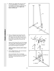
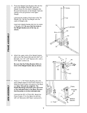
... four 5/16Ó Flat Washers (8), and four 5/16Ó Nylon Locknuts (3). Stack eight Weights (25) on the Base (4) as shown. Press a 2Ó Square Inner Cap (27) into the open end of the Weights are turned so the pin grooves are on the Top Frame. Do not tighten the Nylon...Bolt. 2. Hand tighten a 5/16Ó Nylon Locknut (3) onto each end of the crossbar. Tighten all of the Top Frame (55). Set two Weight Bumpers (19) onto the bracket on the Weight Bumpers (19). Slide the Front Upright (42) onto the 5/16Ó x 2 2 1/2Ó Carriage Bolts (1) in steps 1 through 3. 4....
... four 5/16Ó Flat Washers (8), and four 5/16Ó Nylon Locknuts (3). Stack eight Weights (25) on the Base (4) as shown. Press a 2Ó Square Inner Cap (27) into the open end of the Weights are turned so the pin grooves are on the Top Frame. Do not tighten the Nylon...Bolt. 2. Hand tighten a 5/16Ó Nylon Locknut (3) onto each end of the crossbar. Tighten all of the Top Frame (55). Set two Weight Bumpers (19) onto the bracket on the Weight Bumpers (19). Slide the Front Upright (42) onto the 5/16Ó x 2 2 1/2Ó Carriage Bolts (1) in steps 1 through 3. 4....
English Manual
Page 7
...Bushings should fit onto each welded spacer on the Base (4). Be sure that the pulley is in front of Weights (25). Press the Weight Tube Bumper (64) into the stack of the Weight Guide (62) as shown. 76 Pins Holes 62 Lubricate 63 64 FRAME ASSEMBLY 25 6. Lubricate the insides ...holes in the Base. Be sure that the pins on the indicated side. Press a 1Ó x 7/8Ó Plastic Bushing (75) onto 7 each end of the Weight Tube (63). Pulley 17 Lubricate 59 Lubricate the 3/8Ó x 8Ó Bolt (59). Attach the Press Frame (17) to the Top Frame (55) with the...
...Bushings should fit onto each welded spacer on the Base (4). Be sure that the pulley is in front of Weights (25). Press the Weight Tube Bumper (64) into the stack of the Weight Guide (62) as shown. 76 Pins Holes 62 Lubricate 63 64 FRAME ASSEMBLY 25 6. Lubricate the insides ...holes in the Base. Be sure that the pins on the indicated side. Press a 1Ó x 7/8Ó Plastic Bushing (75) onto 7 each end of the Weight Tube (63). Pulley 17 Lubricate 59 Lubricate the 3/8Ó x 8Ó Bolt (59). Attach the Press Frame (17) to the Top Frame (55) with the...
English Manual
Page 14
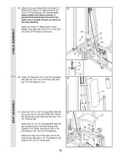
... a 1/4Ó Nylon Locknut (2) and a 1/4Ó Flat Washer (10). Do not com- pletely tighten the Nylon Locknut. CABLE ASSEMBLY 29. Attach the Seat Plate to the Weight Tube (63) with two 1/4Ó x 1/2Ó Screws (18). Attach the Small ÒUÓ-Bracket (67) to the Seat (13) with the 5/16Ó x 1 3/4Ó Bolt...
... a 1/4Ó Nylon Locknut (2) and a 1/4Ó Flat Washer (10). Do not com- pletely tighten the Nylon Locknut. CABLE ASSEMBLY 29. Attach the Seat Plate to the Weight Tube (63) with two 1/4Ó x 1/2Ó Screws (18). Attach the Small ÒUÓ-Bracket (67) to the Seat (13) with the 5/16Ó x 1 3/4Ó Bolt...
English Manual
Page 15
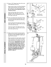
... manual. If there is any slack in ADJUSTMENT, beginning on page 18. 32 44 79 8 3 8 22 40 32 78 Slant must be damaged when heavy weight is oriented as shown. Slide a 5 1/2Ó Pad (30) onto each end of the remaining parts will need to the Press Adjustment Tube (79) with the...
... manual. If there is any slack in ADJUSTMENT, beginning on page 18. 32 44 79 8 3 8 22 40 32 78 Slant must be damaged when heavy weight is oriented as shown. Slide a 5 1/2Ó Pad (30) onto each end of the remaining parts will need to the Press Adjustment Tube (79) with the...
English Manual
Page 16
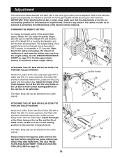
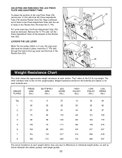
... up for the exercise to be performed. Adjustment The instructions below describe how each part of the home gym system can be changed from the weight setting. If there is any slack in the correct starting position for each exercise. For some exercises, the Chain (52) should be attached between the... REMOVING THE LEG PRESS PLATE AND ADJUSTMENT TUBE and LOCKING THE LEG LEVER on page 17 to find the approximate amount of resistance at each weight station. 25 26 ATTACHING THE LAT BAR OR NYLON STRAP TO THE HIGH PULLEY STATION Attach the Lat Bar (54) to the Long Cable (23...
... up for the exercise to be performed. Adjustment The instructions below describe how each part of the home gym system can be changed from the weight setting. If there is any slack in the correct starting position for each exercise. For some exercises, the Chain (52) should be attached between the... REMOVING THE LEG PRESS PLATE AND ADJUSTMENT TUBE and LOCKING THE LEG LEVER on page 17 to find the approximate amount of resistance at each weight station. 25 26 ATTACHING THE LAT BAR OR NYLON STRAP TO THE HIGH PULLEY STATION Attach the Lat Bar (54) to the Long Cable (23...
English Manual
Page 17
...) through the hole in the Leg Lever and the hole in the Rocker Arm (32). 32 79 78 40 32 40 29 Weight Resistance Chart This chart shows the approximate weight resistance at each butterfly arm. Align a different set of holes in the Press Adjustment Tube with the set of the Leg... Press Plate (78), remove the ÒLÓ-Pin (40) from the Press Adjustment Tube (79) and the Rocker Arm (32). top weight. WEIGHT PLATES PRESS ARM (lbs.) BUTTERFLY ARM (lbs.) LEG LEVER (lbs.) HIGH PULLEY (lbs.) LOW PULLEY (lbs.) LEG PRESS (lbs.) Top 13 1 36 2 57 3 73 4 99...
...) through the hole in the Leg Lever and the hole in the Rocker Arm (32). 32 79 78 40 32 40 29 Weight Resistance Chart This chart shows the approximate weight resistance at each butterfly arm. Align a different set of holes in the Press Adjustment Tube with the set of the Leg... Press Plate (78), remove the ÒLÓ-Pin (40) from the Press Adjustment Tube (79) and the Rocker Arm (32). top weight. WEIGHT PLATES PRESS ARM (lbs.) BUTTERFLY ARM (lbs.) LEG LEVER (lbs.) HIGH PULLEY (lbs.) LOW PULLEY (lbs.) LEG PRESS (lbs.) Top 13 1 36 2 57 3 73 4 99...
English Manual
Page 18
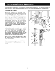
... 2). Be sure that the Cable and Pulley move smoothly. 23 15 Note: If a cable tends to remove the Small ÒUÓ-Bracket (67) from the Weight Tube (not shown) or remove the 3 1/2Ó Pulley (15) from the Long ÒUÓ-Bracket (57). If there is slack in the cables before resistance... cover of cable used on the home gym system, can be tightened. Replace any worn parts immediately. If the cables need to slip off the weight stack. 1 23 67 76 2 Additional slack can stretch slightly when it . Do not use the home gym system. Slack can be removed from the ...
... 2). Be sure that the Cable and Pulley move smoothly. 23 15 Note: If a cable tends to remove the Small ÒUÓ-Bracket (67) from the Weight Tube (not shown) or remove the 3 1/2Ó Pulley (15) from the Long ÒUÓ-Bracket (57). If there is slack in the cables before resistance... cover of cable used on the home gym system, can be tightened. Replace any worn parts immediately. If the cables need to slip off the weight stack. 1 23 67 76 2 Additional slack can stretch slightly when it . Do not use the home gym system. Slack can be removed from the ...
English Manual
Page 19
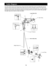
Long Cable (23) 2 1ÑHigh Pulley 7 3 5 4 6 7ÑLong ÒUÓ-Bracket Short Cable (58) Weight StackÑ8 6 5 2 1ÑLow Pulley 4 3 19 The starting and ending points of the Short Cable (58) and the Long Cable (23). If the cables have ...
Long Cable (23) 2 1ÑHigh Pulley 7 3 5 4 6 7ÑLong ÒUÓ-Bracket Short Cable (58) Weight StackÑ8 6 5 2 1ÑLow Pulley 4 3 19 The starting and ending points of the Short Cable (58) and the Long Cable (23). If the cables have ...
English Manual
Page 23
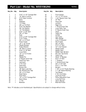
...Rear Upright Long ÒUÓ-Bracket Short Cable 3/8Ó x 8Ó Bolt 5/16Ó x 6Ó Bolt 1/2Ó x 3/4Ó Spacer Weight Guide Weight Tube Weight Tube Bumper #8 x 3/4Ó Tap Screw Cable Trap Small ÒUÓ-Bracket 5/16Ó x 5Ó Bolt 1Ó Retainer 1Ó ...3 3/4Ó Bolt 5/16Ó x 1 3/4Ó Bolt Bumper 1 1/8Ó x 2 1/2Ó Plastic Bushing 1Ó x 7/8Ó Plastic Bushing Top Weight 3 1/2Ó Low Pulley Leg Press Plate Press Adjustment Tube Long Pad Tube UserÕs Manual Exercise Poster Note: Ò#Ó indicates a non-illustrated part. ...
...Rear Upright Long ÒUÓ-Bracket Short Cable 3/8Ó x 8Ó Bolt 5/16Ó x 6Ó Bolt 1/2Ó x 3/4Ó Spacer Weight Guide Weight Tube Weight Tube Bumper #8 x 3/4Ó Tap Screw Cable Trap Small ÒUÓ-Bracket 5/16Ó x 5Ó Bolt 1Ó Retainer 1Ó ...3 3/4Ó Bolt 5/16Ó x 1 3/4Ó Bolt Bumper 1 1/8Ó x 2 1/2Ó Plastic Bushing 1Ó x 7/8Ó Plastic Bushing Top Weight 3 1/2Ó Low Pulley Leg Press Plate Press Adjustment Tube Long Pad Tube UserÕs Manual Exercise Poster Note: Ò#Ó indicates a non-illustrated part. ...


