
English Manual
Page 2
...the above limitation may not apply to you. Remove the EXPLODED DRAWING/PART LIST and the PART IDENTIFICATION CHART before beginning assembly. WEIDER is authorized by ICON. Accordingly, the above limitation may not apply to you specific legal rights. The warranty extended ... days from state to state. This warranty gives you . Table of Contents LIMITED WARRANTY 2 IMPORTANT PRECAUTIONS 3 BEFORE YOU BEGIN 4 ASSEMBLY 5 ADJUSTMENT 16 WEIGHT RESISTANCE CHART 17 TROUBLE-SHOOTING AND MAINTENANCE 18 CABLE DIAGRAM 19 ORDERING REPLACEMENT PARTS Back Cover Note: An EXPLODED...
...the above limitation may not apply to you. Remove the EXPLODED DRAWING/PART LIST and the PART IDENTIFICATION CHART before beginning assembly. WEIDER is authorized by ICON. Accordingly, the above limitation may not apply to you specific legal rights. The warranty extended ... days from state to state. This warranty gives you . Table of Contents LIMITED WARRANTY 2 IMPORTANT PRECAUTIONS 3 BEFORE YOU BEGIN 4 ASSEMBLY 5 ADJUSTMENT 16 WEIGHT RESISTANCE CHART 17 TROUBLE-SHOOTING AND MAINTENANCE 18 CABLE DIAGRAM 19 ORDERING REPLACEMENT PARTS Back Cover Note: An EXPLODED...
English Manual
Page 4
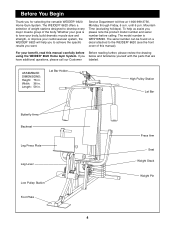
... your goal is WESY85290. For your cardiovascular system, the WEIDER¨ 8620 will help us assist you below and familiarize yourself with ...please note the product model number and serial number before Before reading further, please review the drawing using the WEIDER¨ 8620 Home Gym System. To help you to tone your body, build dramatic muscle size and strength, or improve ... you want. The model number is to achieve the specific results you for selecting the versatile WEIDER¨ 8620 Home Gym System. The serial number can be found on a decal attached to develop every...
... your goal is WESY85290. For your cardiovascular system, the WEIDER¨ 8620 will help us assist you below and familiarize yourself with ...please note the product model number and serial number before Before reading further, please review the drawing using the WEIDER¨ 8620 Home Gym System. To help you to tone your body, build dramatic muscle size and strength, or improve ... you want. The model number is to achieve the specific results you for selecting the versatile WEIDER¨ 8620 Home Gym System. The serial number can be found on a decal attached to develop every...
English Manual
Page 5
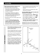
...end of this manual. Press a 2Ó Square Inner Cap (27) into four stages: 1) frame assembly, 2) press and butterfly arm assembly, 3) cable and pulley assembly, and 4) seat and backrest assembly. Before beginning assembly, be more convenient if you have read the following tools: A socket set, a set of open...to do not dispose of the home gym system in the Stabilizer (5). THE FOLLOWING TOOLS (NOT INCLUDED) ARE REQUIRED FOR ASSEMBLY: ¥ Two (2) adjustable wrenches ¥ One (1) standard screwdriver ¥ One (1) phillips screwdriver ¥ One (1) rubber mallet ¥ Lubricant, ...
...end of this manual. Press a 2Ó Square Inner Cap (27) into four stages: 1) frame assembly, 2) press and butterfly arm assembly, 3) cable and pulley assembly, and 4) seat and backrest assembly. Before beginning assembly, be more convenient if you have read the following tools: A socket set, a set of open...to do not dispose of the home gym system in the Stabilizer (5). THE FOLLOWING TOOLS (NOT INCLUDED) ARE REQUIRED FOR ASSEMBLY: ¥ Two (2) adjustable wrenches ¥ One (1) standard screwdriver ¥ One (1) phillips screwdriver ¥ One (1) rubber mallet ¥ Lubricant, ...
English Manual
Page 6
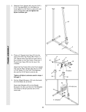
... bracket on the Weight Bumpers (19). Press a 2Ó Square Inner Cap (27) into each Carriage Bolt. Do not tighten the Nylon Locknuts yet. 42 FRAME ASSEMBLY 3 4 1 3. 2. Be sure that all Nylon Locknuts used in the Base (4).
... bracket on the Weight Bumpers (19). Press a 2Ó Square Inner Cap (27) into each Carriage Bolt. Do not tighten the Nylon Locknuts yet. 42 FRAME ASSEMBLY 3 4 1 3. 2. Be sure that all Nylon Locknuts used in the Base (4).
English Manual
Page 7
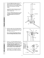
...) to the Top Frame (55) with the 3/8Ó x 8Ó Bolt and a 3/8Ó Nylon Locknut (21). 21 4 ÑTube Welded Spacers 75 7 ARM ASSEMBLY Insert the Weight Tube into place on the Weight Tube are at the top, as shown. 61 3 55 60 20 62 7. The Plastic Bushings should... fit. Press the Weight Tube Bumper (64) into the stack of the Weight Guide (62) as shown. 76 Pins Holes 62 Lubricate 63 64 FRAME ASSEMBLY 25 6. Insert both Weight Guides (62) into the 5 end of the indicated tube in front of Weights (25). Press a 1Ó x 7/8Ó Plastic ...
...) to the Top Frame (55) with the 3/8Ó x 8Ó Bolt and a 3/8Ó Nylon Locknut (21). 21 4 ÑTube Welded Spacers 75 7 ARM ASSEMBLY Insert the Weight Tube into place on the Weight Tube are at the top, as shown. 61 3 55 60 20 62 7. The Plastic Bushings should... fit. Press the Weight Tube Bumper (64) into the stack of the Weight Guide (62) as shown. 76 Pins Holes 62 Lubricate 63 64 FRAME ASSEMBLY 25 6. Insert both Weight Guides (62) into the 5 end of the indicated tube in front of Weights (25). Press a 1Ó x 7/8Ó Plastic ...
English Manual
Page 8
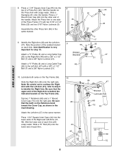
Assemble the other end of a Press Arm (46). Arm identification is behind the indicated bracket on the Top Frame (55). Attach a ÒVÓ-Pulley (6) and a Long ... a 3/8Ó x 2 1/2Ó Bolt (7) and a 3/8Ó Nylon Locknut (21). 8 31 44 49 46 22 9 50 6 Welded Brackets 48 3 17 7 50 6 21 44 49 46 47 ARM ASSEMBLY 10. Identify the Right Arm (48) and the Left Arm (47). Slide the Right Arm (48) onto the right axle. Slide a Handgrip (31) onto the...
Assemble the other end of a Press Arm (46). Arm identification is behind the indicated bracket on the Top Frame (55). Attach a ÒVÓ-Pulley (6) and a Long ... a 3/8Ó x 2 1/2Ó Bolt (7) and a 3/8Ó Nylon Locknut (21). 8 31 44 49 46 22 9 50 6 Welded Brackets 48 3 17 7 50 6 21 44 49 46 47 ARM ASSEMBLY 10. Identify the Right Arm (48) and the Left Arm (47). Slide the Right Arm (48) onto the right axle. Slide a Handgrip (31) onto the...
English Manual
Page 9
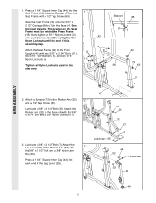
Slide the Seat Frame (36) onto the 5/16Ó x 2 1/2Ó Carriage Bolts (1) in this assembly step. 3 Attach the Seat Frame (36) to the Front Upright (42) with the 3/8Ó x 3 1/4Ó Bolt and a 3/8Ó Nylon Locknut (21). 4 1 73 65 32 21 ...; Flat Washers (8), and two 5/16Ó Nylon Locknuts (3). 11 Tighten all Nylon Locknuts used in the Base (4). Bracket 36 17 44 73 36 65 3 ARM ASSEMBLY 12. The bracket on the Seat Frame must be behind the Press Frame (17). Hand-tighten a 5/16Ó Nylon Locknut (3) 42 onto each end of...
Slide the Seat Frame (36) onto the 5/16Ó x 2 1/2Ó Carriage Bolts (1) in this assembly step. 3 Attach the Seat Frame (36) to the Front Upright (42) with the 3/8Ó x 3 1/4Ó Bolt and a 3/8Ó Nylon Locknut (21). 4 1 73 65 32 21 ...; Flat Washers (8), and two 5/16Ó Nylon Locknuts (3). 11 Tighten all Nylon Locknuts used in the Base (4). Bracket 36 17 44 73 36 65 3 ARM ASSEMBLY 12. The bracket on the Seat Frame must be behind the Press Frame (17). Hand-tighten a 5/16Ó Nylon Locknut (3) 42 onto each end of...
English Manual
Page 10
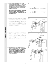
... the Long Cable Trap (50) is between the Pulley and the hook. The pulleys must be able to hold the Cable in place. 17. CABLE ASSEMBLY 14. tioned to the indicated bracket on the Front Upright (42) with the ball is on the Left Arm (47). Be sure that 55 23... 3/8Ó Nylon Locknut (not shown). 7 6 50 42 23 21 6 7 50 47 23 10 Be sure that the Long Cable Trap is in place. IMPORTANT: While assembling the cables, do not overtighten the bolts and nuts securing the pulleys.
... the Long Cable Trap (50) is between the Pulley and the hook. The pulleys must be able to hold the Cable in place. 17. CABLE ASSEMBLY 14. tioned to the indicated bracket on the Front Upright (42) with the ball is on the Left Arm (47). Be sure that 55 23... 3/8Ó Nylon Locknut (not shown). 7 6 50 42 23 21 6 7 50 47 23 10 Be sure that the Long Cable Trap is in place. IMPORTANT: While assembling the cables, do not overtighten the bolts and nuts securing the pulleys.
English Manual
Page 11
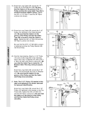
... a 3 1/2Ó Pulley 20 (15) and a Cable Trap (66) to the bracket on the Right Arm (48). Be sure that the Cable is pre-attached. CABLE ASSEMBLY 18. Tighten the 3/8Ó x 2Ó Bolt (12) and the 3/8Ó Nylon Locknut (not shown). Be sure that the Cable is in this 21 step is...
... a 3 1/2Ó Pulley 20 (15) and a Cable Trap (66) to the bracket on the Right Arm (48). Be sure that the Cable is pre-attached. CABLE ASSEMBLY 18. Tighten the 3/8Ó x 2Ó Bolt (12) and the 3/8Ó Nylon Locknut (not shown). Be sure that the Cable is in this 21 step is...
English Manual
Page 12
CABLE ASSEMBLY 22. Wrap the Short Cable (58) around a 3 1/2Ó Pulley (15). Be sure that the Cable Trap is turned to hold the Cable in place and ...
CABLE ASSEMBLY 22. Wrap the Short Cable (58) around a 3 1/2Ó Pulley (15). Be sure that the Cable Trap is turned to hold the Cable in place and ...
English Manual
Page 13
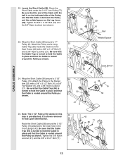
... as shown. Route the Short Cable (58) around the 3 1/2Ó Pulley (15) attached to hold the Cable in the inset drawing. 2 57 10 58 CABLE ASSEMBLY 2 10 57 58 13 Tighten the 3/8Ó Nylon Locknut (21) and the 3/8Ó x 3 3/4Ó Bolt (71). 26 21 66 27 42 9 71 16 9 17 58...
... as shown. Route the Short Cable (58) around the 3 1/2Ó Pulley (15) attached to hold the Cable in the inset drawing. 2 57 10 58 CABLE ASSEMBLY 2 10 57 58 13 Tighten the 3/8Ó Nylon Locknut (21) and the 3/8Ó x 3 3/4Ó Bolt (71). 26 21 66 27 42 9 71 16 9 17 58...
English Manual
Page 14
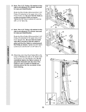
...; Screws (43) and 30 two 1/4Ó Flat Washers (10). 23 10 2 67 42 41 43 10 SEAT ASSEMBLY 31. Attach the Seat Plate to the Weight Tube (63) with two 1/4Ó x 1/2Ó Screws (18). CABLE ASSEMBLY 29. Tighten a 1/4Ó Nylon Locknut (2) with a 1/4Ó Flat Washer (10) and the 1/4Ó x 2 1/4Ó Screw (24...
...; Screws (43) and 30 two 1/4Ó Flat Washers (10). 23 10 2 67 42 41 43 10 SEAT ASSEMBLY 31. Attach the Seat Plate to the Weight Tube (63) with two 1/4Ó x 1/2Ó Screws (18). CABLE ASSEMBLY 29. Tighten a 1/4Ó Nylon Locknut (2) with a 1/4Ó Flat Washer (10) and the 1/4Ó x 2 1/4Ó Screw (24...
English Manual
Page 15
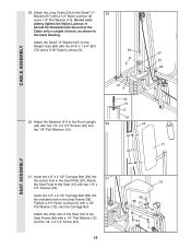
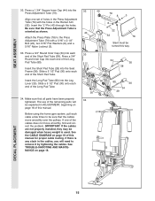
... on page 18. 32 44 79 8 3 8 22 40 32 78 Slant must be sure that the cables move smoothly, find and correct the problem. SEAT ASSEMBLY 32. Press a 1 3/4Ó Square Inner Cap (44) into each end of this way 33 34 30 28 36 30 34 80 30 34 29 DECAL...
... on page 18. 32 44 79 8 3 8 22 40 32 78 Slant must be sure that the cables move smoothly, find and correct the problem. SEAT ASSEMBLY 32. Press a 1 3/4Ó Square Inner Cap (44) into each end of this way 33 34 30 28 36 30 34 80 30 34 29 DECAL...
English Manual
Page 19
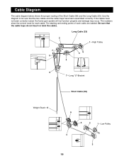
If the cables have been assembled correctly. Be sure that the two cables and the cable traps have not been correctly routed, the home gym system will not function properly and ...
If the cables have been assembled correctly. Be sure that the two cables and the cable traps have not been correctly routed, the home gym system will not function properly and ...


