
English Manual
Page 2
...all other rights which warranty claim is limited in workmanship and material, under this product to state. This warranty gives you . WEIDER is not responsible or liable for a period of ninety (90) days from state to be pre-authorized by an ICON authorized...Contents LIMITED WARRANTY 2 IMPORTANT PRECAUTIONS 3 BEFORE YOU BEGIN 4 ASSEMBLY 5 ADJUSTMENT 16 WEIGHT RESISTANCE CHART 17 TROUBLE-SHOOTING AND MAINTENANCE 18 CABLE DIAGRAM 19 ORDERING REPLACEMENT PARTS Back Cover Note: An EXPLODED DRAWING/PART LIST and a PART IDENTIFICATION CHART are attached to the original purchaser....
...all other rights which warranty claim is limited in workmanship and material, under this product to state. This warranty gives you . WEIDER is not responsible or liable for a period of ninety (90) days from state to be pre-authorized by an ICON authorized...Contents LIMITED WARRANTY 2 IMPORTANT PRECAUTIONS 3 BEFORE YOU BEGIN 4 ASSEMBLY 5 ADJUSTMENT 16 WEIGHT RESISTANCE CHART 17 TROUBLE-SHOOTING AND MAINTENANCE 18 CABLE DIAGRAM 19 ORDERING REPLACEMENT PARTS Back Cover Note: An EXPLODED DRAWING/PART LIST and a PART IDENTIFICATION CHART are attached to the original purchaser....
English Manual
Page 10
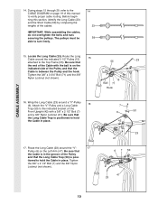
...29, refer to the CABLE DIAGRAM on page 19 of the cables. The pulleys must be able to the Top Frame (55). Be sure that 55 23 the end of the Cable with a 3/8Ó x 2 1/2Ó Bolt (7) and a 3/8Ó Nylon Locknut (21). Be sure that the Cable is on the Left Arm...211; Nylon Locknut (not shown). 15 Ball 71 Hook 16. Wrap the Long Cable (23) around the ÒVÓ- 17 Pulley (6) on the indicated side of the Pulley and that the Cable is posi- CABLE ASSEMBLY 14. Locate the Long Cable (23). Tighten the 3/8Ó x 2 1/2Ó Bolt (7) and the 3/8Ó...
...29, refer to the CABLE DIAGRAM on page 19 of the cables. The pulleys must be able to the Top Frame (55). Be sure that 55 23 the end of the Cable with a 3/8Ó x 2 1/2Ó Bolt (7) and a 3/8Ó Nylon Locknut (21). Be sure that the Cable is on the Left Arm...211; Nylon Locknut (not shown). 15 Ball 71 Hook 16. Wrap the Long Cable (23) around the ÒVÓ- 17 Pulley (6) on the indicated side of the Pulley and that the Cable is posi- CABLE ASSEMBLY 14. Locate the Long Cable (23). Tighten the 3/8Ó x 2 1/2Ó Bolt (7) and the 3/8Ó...
English Manual
Page 15
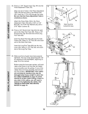
... (80) into the Seat Frame (36). If there is any slack in the cables, you will be explained in the Rocker Arm (32). The use of the remaining parts will need... to remove it by tightening the cables. Attach the Press Plate (78) to be damaged when heavy weight is oriented as shown. Slide ...the pulleys. See TROUBLE-SHOOTING AND MAINTENANCE on page 16 of this manual. See the CABLE DIAGRAM on page 19 of this manual for proper cable routing. Insert the ÒLÓ-Pin (40) through the holes. Press a 3/4Ó...
... (80) into the Seat Frame (36). If there is any slack in the cables, you will be explained in the Rocker Arm (32). The use of the remaining parts will need... to remove it by tightening the cables. Attach the Press Plate (78) to be damaged when heavy weight is oriented as shown. Slide ...the pulleys. See TROUBLE-SHOOTING AND MAINTENANCE on page 16 of this manual. See the CABLE DIAGRAM on page 19 of this manual for proper cable routing. Insert the ÒLÓ-Pin (40) through the holes. Press a 3/4Ó...
English Manual
Page 19
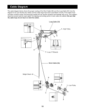
Cable Diagram The cable diagram below shows the proper routing of each cable. Long Cable (23) 2 1ÑHigh Pulley 7 3 5 4 6 7ÑLong ÒUÓ-Bracket Short Cable (58) Weight StackÑ8 6 5 2 1ÑLow Pulley 4 3 19 Be sure that the two cables and the cable traps have not been correctly routed, the home gym... may occur. The starting and ending points of the Short Cable (58) and the Long Cable (23). Use the diagram to be sure that the cable traps do not touch or bind the cables. If the cables have been assembled correctly. The numbers show the correct route ...
Cable Diagram The cable diagram below shows the proper routing of each cable. Long Cable (23) 2 1ÑHigh Pulley 7 3 5 4 6 7ÑLong ÒUÓ-Bracket Short Cable (58) Weight StackÑ8 6 5 2 1ÑLow Pulley 4 3 19 Be sure that the two cables and the cable traps have not been correctly routed, the home gym... may occur. The starting and ending points of the Short Cable (58) and the Long Cable (23). Use the diagram to be sure that the cable traps do not touch or bind the cables. If the cables have been assembled correctly. The numbers show the correct route ...


