
English Manual
Page 1
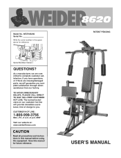
... instructions in the space above for future reference. The trained technicians on our customer hot line will guarantee you complete satisfaction through direct assistance from our factory. Save this equipment. Serial Number Decal QUESTIONS? PATENT PENDING USERÕS MANUAL As a manufacturer, we will provide immediate assistance, free of charge to you have questions, or if there are missing/damaged parts...
... instructions in the space above for future reference. The trained technicians on our customer hot line will guarantee you complete satisfaction through direct assistance from our factory. Save this equipment. Serial Number Decal QUESTIONS? PATENT PENDING USERÕS MANUAL As a manufacturer, we will provide immediate assistance, free of charge to you have questions, or if there are missing/damaged parts...
English Manual
Page 2
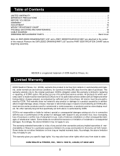
... warranty lasts. Table of Contents LIMITED WARRANTY 2 IMPORTANT PRECAUTIONS 3 BEFORE YOU BEGIN 4 ASSEMBLY 5 ADJUSTMENT 16 WEIGHT RESISTANCE CHART 17 TROUBLE-SHOOTING AND MAINTENANCE 18 CABLE DIAGRAM 19 ORDERING REPLACEMENT PARTS Back Cover Note: An EXPLODED DRAWING/PART LIST and a PART IDENTIFICATION CHART are attached to the center of this warranty is made must be pre-authorized by an ICON authorized service center, products used for commercial or rental purposes, or products used as store display models. This warranty...
... warranty lasts. Table of Contents LIMITED WARRANTY 2 IMPORTANT PRECAUTIONS 3 BEFORE YOU BEGIN 4 ASSEMBLY 5 ADJUSTMENT 16 WEIGHT RESISTANCE CHART 17 TROUBLE-SHOOTING AND MAINTENANCE 18 CABLE DIAGRAM 19 ORDERING REPLACEMENT PARTS Back Cover Note: An EXPLODED DRAWING/PART LIST and a PART IDENTIFICATION CHART are attached to the center of this warranty is made must be pre-authorized by an ICON authorized service center, products used for commercial or rental purposes, or products used as store display models. This warranty...
English Manual
Page 3
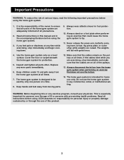
... home gym system are raised. Never release the press arm, butterfly arms, leg lever, lat bar, leg press plate, or nylon strap while weights are adequately informed of the pulleys. 13. Inspect and tighten all of all instructions in this manual and in any time while exercising, stop immediately and make sure that does not use only. If the cables bind while you feel pain or dizziness at all times. Replace any exercise program...
... home gym system are raised. Never release the press arm, butterfly arms, leg lever, lat bar, leg press plate, or nylon strap while weights are adequately informed of the pulleys. 13. Inspect and tighten all of all instructions in this manual and in any time while exercising, stop immediately and make sure that does not use only. If the cables bind while you feel pain or dizziness at all times. Replace any exercise program...
English Manual
Page 4
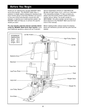
... model number and serial number before Before reading further, please review the drawing using the WEIDER¨ 8620 Home Gym System. Whether your benefit, read this manual). For your goal is WESY85290. Lat Bar Holder High Pulley Station Lat Bar Butterfly Arms Backrest Leg Press Plate Leg Lever Low Pulley Station Foot Plate 4 Press Arm Seat Weight Stack Weight Pin Length: 59 in . Service Department toll-free at 1-800-999-3756, Monday through Friday, 6 a.m. The model number is to the WEIDER¨ 8620...
... model number and serial number before Before reading further, please review the drawing using the WEIDER¨ 8620 Home Gym System. Whether your benefit, read this manual). For your goal is WESY85290. Lat Bar Holder High Pulley Station Lat Bar Butterfly Arms Backrest Leg Press Plate Leg Lever Low Pulley Station Foot Plate 4 Press Arm Seat Weight Stack Weight Pin Length: 59 in . Service Department toll-free at 1-800-999-3756, Monday through Friday, 6 a.m. The model number is to the WEIDER¨ 8620...
English Manual
Page 5
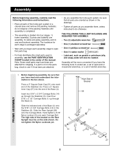
... butterfly arm assembly, 3) cable and pulley assembly, and 4) seat and backrest assembly. Insert two 5/16Ó x 2 3/4Ó Carriage Bolts (14) up through the Stabilizer (5). Hand tighten a 5/16Ó Nylon Locknut (3) onto each assembly stage to open -end or closed-end wrenches, or a set of open that all parts are oriented as shown in the drawings. ¥ Tighten all parts of the home gym system in a cleared area and remove...
... butterfly arm assembly, 3) cable and pulley assembly, and 4) seat and backrest assembly. Insert two 5/16Ó x 2 3/4Ó Carriage Bolts (14) up through the Stabilizer (5). Hand tighten a 5/16Ó Nylon Locknut (3) onto each assembly stage to open -end or closed-end wrenches, or a set of open that all parts are oriented as shown in the drawings. ¥ Tighten all parts of the home gym system in a cleared area and remove...
English Manual
Page 6
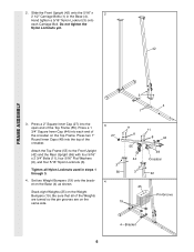
... FRAME ASSEMBLY 3 4 1 3. Press a 1 3/4Ó Square Inner Cap (44) into the open end of the Weights are turned so the pin grooves are on the Top Frame. Be sure that all Nylon Locknuts used in the Base (4). Slide the Front Upright (42) onto the 5/16Ó x 2 2 1/2Ó Carriage Bolts (1) in steps 1 through 3. 4. Press a 2Ó Square Inner Cap (27) into each Carriage Bolt. Tighten all...
... FRAME ASSEMBLY 3 4 1 3. Press a 1 3/4Ó Square Inner Cap (44) into the open end of the Weights are turned so the pin grooves are on the Top Frame. Be sure that all Nylon Locknuts used in the Base (4). Slide the Front Upright (42) onto the 5/16Ó x 2 2 1/2Ó Carriage Bolts (1) in steps 1 through 3. 4. Press a 2Ó Square Inner Cap (27) into each Carriage Bolt. Tighten all...
English Manual
Page 8
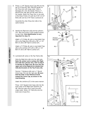
... Press Arm with a 3/8Ó x 2 1/2Ó Bolt (7) and a 3/8Ó Nylon Locknut (21). 8 31 44 49 46 22 9 50 6 Welded Brackets 48 3 17 7 50 6 21 44 49 46 47 ARM ASSEMBLY 10. Slide a 10Ó Pad (45) onto the lower end of a Press Arm (46). Press a 1Ó Round Inner Cap (49) into the lower ends of the handle. Attach a ÒVÓ-Pulley (6) and a Long Cable...
... Press Arm with a 3/8Ó x 2 1/2Ó Bolt (7) and a 3/8Ó Nylon Locknut (21). 8 31 44 49 46 22 9 50 6 Welded Brackets 48 3 17 7 50 6 21 44 49 46 47 ARM ASSEMBLY 10. Slide a 10Ó Pad (45) onto the lower end of a Press Arm (46). Press a 1Ó Round Inner Cap (49) into the lower ends of the handle. Attach a ÒVÓ-Pulley (6) and a Long Cable...
English Manual
Page 9
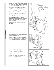
...; x 2 1/2Ó Carriage Bolts (1) in this assembly step. 3 Attach the Seat Frame (36) to the Seat Frame with a 1/2Ó Tap Screw (65). 12 Lubricate a 3/8Ó x 3 1/4Ó Bolt (35). Bracket 36 17 44 73 36 65 3 ARM ASSEMBLY 12. 11. Do not tighten the Nylon Locknuts until the end of the Leg Lever (29). 4 LubricateÑ35 13 44 32 7ÑLubricate 33 29 44 9 Press a 1 3/4Ó Square...
...; x 2 1/2Ó Carriage Bolts (1) in this assembly step. 3 Attach the Seat Frame (36) to the Seat Frame with a 1/2Ó Tap Screw (65). 12 Lubricate a 3/8Ó x 3 1/4Ó Bolt (35). Bracket 36 17 44 73 36 65 3 ARM ASSEMBLY 12. 11. Do not tighten the Nylon Locknuts until the end of the Leg Lever (29). 4 LubricateÑ35 13 44 32 7ÑLubricate 33 29 44 9 Press a 1 3/4Ó Square...
English Manual
Page 10
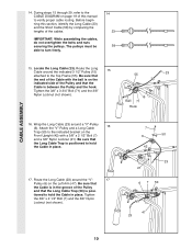
.... Tighten the 3/8Ó x 2 1/2Ó Bolt (7) and the 3/8Ó Nylon Locknut (not shown). 7 6 50 42 23 21 6 7 50 47 23 10 IMPORTANT: While assembling the cables, do not overtighten the bolts and nuts securing the pulleys. Route the Long Cable around a ÒVÓ-Pulley (6). During steps 15 through 29, refer to verify proper cable routing. Before beginning this manual to the CABLE DIAGRAM on the Left Arm...
.... Tighten the 3/8Ó x 2 1/2Ó Bolt (7) and the 3/8Ó Nylon Locknut (not shown). 7 6 50 42 23 21 6 7 50 47 23 10 IMPORTANT: While assembling the cables, do not overtighten the bolts and nuts securing the pulleys. Route the Long Cable around a ÒVÓ-Pulley (6). During steps 15 through 29, refer to verify proper cable routing. Before beginning this manual to the CABLE DIAGRAM on the Left Arm...
English Manual
Page 11
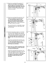
... 21 step is in place. Be sure that the Cable and Pulley move 21 smoothly. 11 Tighten the 3/8Ó x 2Ó Bolt (12) 55 and the 3/8Ó Nylon Locknut (21). Be sure that the Cable is turned to the indicated hole in the groove of the Pulley and that the Cable Trap is shown removed for easy part identification. 23 15 Bracket 12 Route...
... 21 step is in place. Be sure that the Cable and Pulley move 21 smoothly. 11 Tighten the 3/8Ó x 2Ó Bolt (12) 55 and the 3/8Ó Nylon Locknut (21). Be sure that the Cable is turned to the indicated hole in the groove of the Pulley and that the Cable Trap is shown removed for easy part identification. 23 15 Bracket 12 Route...
English Manual
Page 12
... the Cable is routed around the Pulley as shown. Tighten the 3/8Ó x 3 1/2Ó Bolt (16) and the 3/8Ó Nylon Locknut (not shown). 23. Attach the Pulley and a Long 23 Cable Trap (50) inside the bracket on the Leg Lever (29). Wrap the Short Cable (58) around a ÒVÓ- It is pre-attached. CABLE ASSEMBLY 22. Attach the Pulley to the lower hole in the Front Upright (42...
... the Cable is routed around the Pulley as shown. Tighten the 3/8Ó x 3 1/2Ó Bolt (16) and the 3/8Ó Nylon Locknut (not shown). 23. Attach the Pulley and a Long 23 Cable Trap (50) inside the bracket on the Leg Lever (29). Wrap the Short Cable (58) around a ÒVÓ- It is pre-attached. CABLE ASSEMBLY 22. Attach the Pulley to the lower hole in the Front Upright (42...
English Manual
Page 13
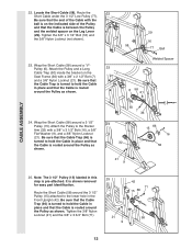
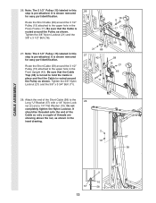
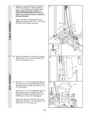
... Upright (42). Do not completely tighten the Nylon Locknut. Route the Short Cable (58) around the Pulley as shown. Be sure that the Cable is shown removed for easy part identification. Tighten the 3/8Ó Nylon Locknut (21) and the 3/8Ó x 3 1/2Ó Bolt (16). 27. Be sure that the Cable is pre-attached. Route the Short Cable (58) around the Pulley as shown in this step is routed...
... Upright (42). Do not completely tighten the Nylon Locknut. Route the Short Cable (58) around the Pulley as shown. Be sure that the Cable is shown removed for easy part identification. Tighten the 3/8Ó Nylon Locknut (21) and the 3/8Ó x 3 1/2Ó Bolt (16). 27. Be sure that the Cable is pre-attached. Route the Short Cable (58) around the Pulley as shown in this step is routed...
English Manual
Page 14
... 13 38 36 37 10 24 18 2 Tighten a 1/4Ó Nylon Locknut (2) with a 1/4Ó Nylon Locknut (2) and a 1/4Ó Flat Washer (10). Attach the Seat Plate to the Seat Frame (36) with two 1/4Ó x 1/2Ó Screws (18). Attach the Long Cable (23) to the Small ÒUÓ- 29 Bracket (67) with a 1/4Ó Flat Washer (10) onto the Carriage Bolt. CABLE ASSEMBLY 29.
... 13 38 36 37 10 24 18 2 Tighten a 1/4Ó Nylon Locknut (2) with a 1/4Ó Nylon Locknut (2) and a 1/4Ó Flat Washer (10). Attach the Seat Plate to the Seat Frame (36) with two 1/4Ó x 1/2Ó Screws (18). Attach the Long Cable (23) to the Small ÒUÓ- 29 Bracket (67) with a 1/4Ó Flat Washer (10) onto the Carriage Bolt. CABLE ASSEMBLY 29.
English Manual
Page 15
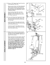
... there is used. If one set of the remaining parts will need to remove it by tightening the cables. Attach the Press Plate (78) to be turned this manual. IMPORTANT: If the cables are not properly installed, they may be explained in ADJUSTMENT, beginning on page 16 of this manual for proper cable routing. Be sure that all parts have been properly tightened. See TROUBLE-SHOOTING AND MAINTENANCE on page 19...
... there is used. If one set of the remaining parts will need to remove it by tightening the cables. Attach the Press Plate (78) to be turned this manual. IMPORTANT: If the cables are not properly installed, they may be explained in ADJUSTMENT, beginning on page 16 of this manual for proper cable routing. Be sure that all parts have been properly tightened. See TROUBLE-SHOOTING AND MAINTENANCE on page 19...
English Manual
Page 16
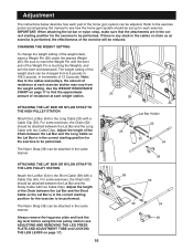
... STRAP TO THE HIGH PULLEY STATION Attach the Lat Bar (54) to be performed. For some exercises, the Chain (52) should be set up for the exercise to the Long Cable (23) with two Cable Clips. The Nylon Strap (39) can be adjusted. Always remove the leg press plate and lock the leg lever before using the low pulley station (see how the home gym system should be performed. Adjustment The instructions...
... STRAP TO THE HIGH PULLEY STATION Attach the Lat Bar (54) to be performed. For some exercises, the Chain (52) should be set up for the exercise to the Long Cable (23) with two Cable Clips. The Nylon Strap (39) can be adjusted. Always remove the leg press plate and lock the leg lever before using the low pulley station (see how the home gym system should be performed. Adjustment The instructions...
English Manual
Page 17
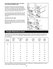
... the 12.5 lb. Weight resistance shown for each butterfly arm. For some exercises, the Press Adjustment Tube (79) must be removed. Align a different set of holes in the Press Adjustment Tube with the set of the Leg Press Plate (78), remove the ÒLÓ-Pin (40) from the Press Adjustment Tube (79) and the Rocker Arm (32). Re-insert the ÒLÓ-Pin. Lift the Press Adjustment Tube off the bracket...
... the 12.5 lb. Weight resistance shown for each butterfly arm. For some exercises, the Press Adjustment Tube (79) must be removed. Align a different set of holes in the Press Adjustment Tube with the set of the Leg Press Plate (78), remove the ÒLÓ-Pin (40) from the Press Adjustment Tube (79) and the Rocker Arm (32). Re-insert the ÒLÓ-Pin. Lift the Press Adjustment Tube off the bracket...
English Manual
Page 18
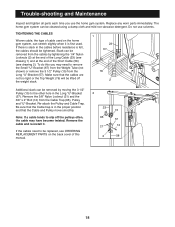
...-install it is felt, the cables should be lifted off the pulleys often, the cable may need to remove the Small ÒUÓ-Bracket (67) from the Weight Tube (not shown) or remove the 3 1/2Ó Pulley (15) from the Long ÒUÓ-Bracket (57). Trouble-shooting and Maintenance Inspect and tighten all parts each time you may have become twisted. Do not use the home gym...
...-install it is felt, the cables should be lifted off the pulleys often, the cable may need to remove the Small ÒUÓ-Bracket (67) from the Weight Tube (not shown) or remove the 3 1/2Ó Pulley (15) from the Long ÒUÓ-Bracket (57). Trouble-shooting and Maintenance Inspect and tighten all parts each time you may have become twisted. Do not use the home gym...
English Manual
Page 19
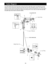
... two cables and the cable traps have not been correctly routed, the home gym system will not function properly and damage may occur. Cable Diagram The cable diagram below shows the proper routing of each cable. If the cables have been assembled correctly. The numbers show the correct route for each cable are labeled. Long Cable (23) 2 1ÑHigh Pulley 7 3 5 4 6 7ÑLong ÒUÓ-Bracket Short Cable (58) Weight Stack...
... two cables and the cable traps have not been correctly routed, the home gym system will not function properly and damage may occur. Cable Diagram The cable diagram below shows the proper routing of each cable. If the cables have been assembled correctly. The numbers show the correct route for each cable are labeled. Long Cable (23) 2 1ÑHigh Pulley 7 3 5 4 6 7ÑLong ÒUÓ-Bracket Short Cable (58) Weight Stack...
English Manual
Page 23
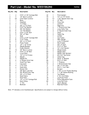
... Lat Bar Top Frame Rear Upright Long ÒUÓ-Bracket Short Cable 3/8Ó x 8Ó Bolt 5/16Ó x 6Ó Bolt 1/2Ó x 3/4Ó Spacer Weight Guide Weight Tube Weight Tube Bumper #8 x 3/4Ó Tap Screw Cable Trap Small ÒUÓ-Bracket 5/16Ó x 5Ó Bolt 1Ó Retainer 1Ó Round Cover Cap 3/8Ó x 3 3/4Ó Bolt 5/16Ó x 1 3/4Ó Bolt Bumper 1 1/8Ó x 2 1/2Ó Plastic Bushing 1Ó x 7/8Ó Plastic Bushing Top Weight 3 1/2Ó Low Pulley Leg Press...
... Lat Bar Top Frame Rear Upright Long ÒUÓ-Bracket Short Cable 3/8Ó x 8Ó Bolt 5/16Ó x 6Ó Bolt 1/2Ó x 3/4Ó Spacer Weight Guide Weight Tube Weight Tube Bumper #8 x 3/4Ó Tap Screw Cable Trap Small ÒUÓ-Bracket 5/16Ó x 5Ó Bolt 1Ó Retainer 1Ó Round Cover Cap 3/8Ó x 3 3/4Ó Bolt 5/16Ó x 1 3/4Ó Bolt Bumper 1 1/8Ó x 2 1/2Ó Plastic Bushing 1Ó x 7/8Ó Plastic Bushing Top Weight 3 1/2Ó Low Pulley Leg Press...
English Manual
Page 25
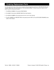
... part(s) (see the front cover of this manual). Part No. 156863 J01539-C R0699A Printed in Canada © 1999 ICON Health & Fitness, Inc. The MODEL NUMBER of the product (WEIDER¨ 8620 Home Gym System). 3. Mountain Time (excluding holidays). The SERIAL NUMBER of the product (see the PART LIST and EXPLODED DRAWING at 1-800-999-3756, Monday through Friday, 6 a.m. Ordering Replacement Parts To order replacement parts, simply call our Customer Service Department toll-free...
... part(s) (see the front cover of this manual). Part No. 156863 J01539-C R0699A Printed in Canada © 1999 ICON Health & Fitness, Inc. The MODEL NUMBER of the product (WEIDER¨ 8620 Home Gym System). 3. Mountain Time (excluding holidays). The SERIAL NUMBER of the product (see the PART LIST and EXPLODED DRAWING at 1-800-999-3756, Monday through Friday, 6 a.m. Ordering Replacement Parts To order replacement parts, simply call our Customer Service Department toll-free...


