
English Manual
Page 2
... PRECAUTIONS 3 BEFORE YOU BEGIN 4 ASSEMBLY 5 ADJUSTMENT 16 WEIGHT RESISTANCE CHART 17 TROUBLE-SHOOTING AND MAINTENANCE 18 CABLE DIAGRAM 19 ORDERING REPLACEMENT PARTS Back Cover Note: An EXPLODED DRAWING/PART LIST and a PART IDENTIFICATION CHART are attached to the center of ICON Health & Fitness, Inc. WEIDER is not responsible or liable for a period...
... PRECAUTIONS 3 BEFORE YOU BEGIN 4 ASSEMBLY 5 ADJUSTMENT 16 WEIGHT RESISTANCE CHART 17 TROUBLE-SHOOTING AND MAINTENANCE 18 CABLE DIAGRAM 19 ORDERING REPLACEMENT PARTS Back Cover Note: An EXPLODED DRAWING/PART LIST and a PART IDENTIFICATION CHART are attached to the center of ICON Health & Fitness, Inc. WEIDER is not responsible or liable for a period...
English Manual
Page 3
... for protection. 5. Never release the press arm, butterfly arms, leg lever, lat bar, leg press plate, or nylon strap while weights are adequately informed of all instructions before using. The weights will fall with pre-existing health problems. Read all precautions. 2. Replace any time while exercising, stop immediately and make sure that...
... for protection. 5. Never release the press arm, butterfly arms, leg lever, lat bar, leg press plate, or nylon strap while weights are adequately informed of all instructions before using. The weights will fall with pre-existing health problems. Read all precautions. 2. Replace any time while exercising, stop immediately and make sure that...
English Manual
Page 4
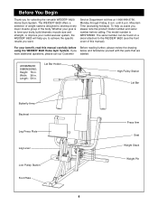
... group of this manual carefully before calling. If you for selecting the versatile WEIDER¨ 8620 Home Gym System. ASSEMBLED DIMENSIONS: Height: 76 in . Whether your goal is WESY85290. The WEIDER¨ 8620 offers a selection of weight stations designed to the WEIDER¨ 8620 (see the front cover of the body. Before You Begin Thank you below...
... group of this manual carefully before calling. If you for selecting the versatile WEIDER¨ 8620 Home Gym System. ASSEMBLED DIMENSIONS: Height: 76 in . Whether your goal is WESY85290. The WEIDER¨ 8620 offers a selection of weight stations designed to the WEIDER¨ 8620 (see the front cover of the body. Before You Begin Thank you below...
English Manual
Page 6
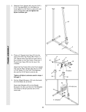
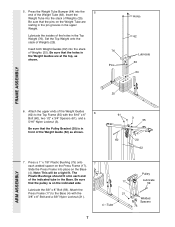
Press a 1 3/4Ó Square Inner Cap (44) into each Carriage Bolt. Set two Weight Bumpers (19) onto the bracket on the Top Frame. Stack eight Weights (25) on the same side. 3 27 11 8 11 8 44 55 44 3 56 3 49 Crossbar 42 4 25 Pin Groove 19 4ÑBracket 6 2. Do not ... x 2 2 1/2Ó Carriage Bolts (1) in steps 1 through 3. 4. Press two 1Ó Round Inner Caps (49) into the open end of the Weights are turned so the pin grooves are on the Weight Bumpers (19). Tighten all of the Top Frame (55). Press a 2Ó Square Inner Cap (27) into the top of the crossbar...
Press a 1 3/4Ó Square Inner Cap (44) into each Carriage Bolt. Set two Weight Bumpers (19) onto the bracket on the Top Frame. Stack eight Weights (25) on the same side. 3 27 11 8 11 8 44 55 44 3 56 3 49 Crossbar 42 4 25 Pin Groove 19 4ÑBracket 6 2. Do not ... x 2 2 1/2Ó Carriage Bolts (1) in steps 1 through 3. 4. Press two 1Ó Round Inner Caps (49) into the open end of the Weights are turned so the pin grooves are on the Weight Bumpers (19). Tighten all of the Top Frame (55). Press a 2Ó Square Inner Cap (27) into the top of the crossbar...
English Manual
Page 7
...a tight fit. Be sure that the Pulley Bracket (20) is on the Press Frame (17). Slide the Press Frame into the 5 end of the Weight Guide (62) as shown. 76 Pins Holes 62 Lubricate 63 64 FRAME ASSEMBLY 25 6. Pulley 17 Lubricate 59 Lubricate the 3/8Ó x 8Ó Bolt... 3 55 60 20 62 7. Press a 1Ó x 7/8Ó Plastic Bushing (75) onto 7 each end of the holes in the Base. 5. Set the Top Weight onto the stack of the Weight Guides (62) to the Base (4) with the 5/16Ó x 6Ó 6 Bolt (60), two 1/2Ó x 3/4Ó Spacers (61), and a 5/16&#...
...a tight fit. Be sure that the Pulley Bracket (20) is on the Press Frame (17). Slide the Press Frame into the 5 end of the Weight Guide (62) as shown. 76 Pins Holes 62 Lubricate 63 64 FRAME ASSEMBLY 25 6. Pulley 17 Lubricate 59 Lubricate the 3/8Ó x 8Ó Bolt... 3 55 60 20 62 7. Press a 1Ó x 7/8Ó Plastic Bushing (75) onto 7 each end of the holes in the Base. 5. Set the Top Weight onto the stack of the Weight Guides (62) to the Base (4) with the 5/16Ó x 6Ó 6 Bolt (60), two 1/2Ó x 3/4Ó Spacers (61), and a 5/16&#...
English Manual
Page 14
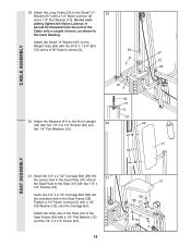
... 36 37 10 24 18 2 Attach the other end of turns, as shown in the Seat Plate (37). Attach the Long Cable (23) to the Weight Tube (63) with two 1/4Ó x 1/2Ó Screws (18).
... 36 37 10 24 18 2 Attach the other end of turns, as shown in the Seat Plate (37). Attach the Long Cable (23) to the Weight Tube (63) with two 1/4Ó x 1/2Ó Screws (18).
English Manual
Page 15
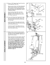
... a 5 1/2Ó Pad (30) onto each end of holes in ADJUSTMENT, beginning on page 16 of the remaining parts will need to be damaged when heavy weight is used. Before using the home gym system, pull each cable a few times to remove it by tightening the cables. See TROUBLE-SHOOTING AND MAINTENANCE...
... a 5 1/2Ó Pad (30) onto each end of holes in ADJUSTMENT, beginning on page 16 of the remaining parts will need to be damaged when heavy weight is used. Before using the home gym system, pull each cable a few times to remove it by tightening the cables. See TROUBLE-SHOOTING AND MAINTENANCE...
English Manual
Page 16
... the length of the Chain between the Lat Bar and the Long Cable so the Lat Bar is touching the Weights, and turn the bent end downward. The weight setting of the weight stack can be performed. IMPORTANT: When attaching the lat bar or nylon strap, make sure that the attachments are ...in increments of the weight stack, insert a Weight Pin (26) under the desired Weight (25). Adjust the length of the Chain between the Lat Bar and the Short Cable so the Lat Bar is performed, ...
... the length of the Chain between the Lat Bar and the Long Cable so the Lat Bar is touching the Weights, and turn the bent end downward. The weight setting of the weight stack can be performed. IMPORTANT: When attaching the lat bar or nylon strap, make sure that the attachments are ...in increments of the weight stack, insert a Weight Pin (26) under the desired Weight (25). Adjust the length of the Chain between the Lat Bar and the Short Cable so the Lat Bar is performed, ...
English Manual
Page 17
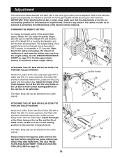
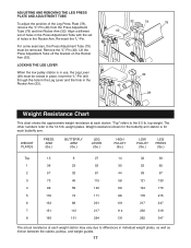
... ADJUSTMENT TUBE To adjust the position of holes in the Rocker Arm. Lift the Press Adjustment Tube off the bracket on the Rocker Arm (32). WEIGHT PLATES PRESS ARM (lbs.) BUTTERFLY ARM (lbs.) LEG LEVER (lbs.) HIGH PULLEY (lbs.) LOW PULLEY (lbs.) LEG PRESS (lbs.) Top 13 1 36 2 57 3 73 4 99... 74 171 88 178 215 88 201 101 217 247 112 217 114 230 319 131 264 131 262 347 The actual resistance at each weight station may vary due to differences in place. LOCKING THE LEG LEVER When the low pulley station is for the butterfly arm station is in...
... ADJUSTMENT TUBE To adjust the position of holes in the Rocker Arm. Lift the Press Adjustment Tube off the bracket on the Rocker Arm (32). WEIGHT PLATES PRESS ARM (lbs.) BUTTERFLY ARM (lbs.) LEG LEVER (lbs.) HIGH PULLEY (lbs.) LOW PULLEY (lbs.) LEG PRESS (lbs.) Top 13 1 36 2 57 3 73 4 99... 74 171 88 178 215 88 201 101 217 247 112 217 114 230 319 131 264 131 262 347 The actual resistance at each weight station may vary due to differences in place. LOCKING THE LEG LEVER When the low pulley station is for the butterfly arm station is in...
English Manual
Page 18
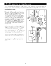
... used . Remove the cable and re-install it is felt, the cables should be replaced, see drawing 2). If the cables need to slip off the weight stack. 1 23 67 76 2 Additional slack can be removed from the cables by tightening the 1/4Ó Nylon Locknuts (2) at the end of the Long Cable... position and that the Cable and Pulley move smoothly. 23 15 Note: If a cable tends to remove the Small ÒUÓ-Bracket (67) from the Weight Tube (not shown) or remove the 3 1/2Ó Pulley (15) from the Long ÒUÓ-Bracket (57). TIGHTENING THE CABLES Woven cable, the type of this...
... used . Remove the cable and re-install it is felt, the cables should be replaced, see drawing 2). If the cables need to slip off the weight stack. 1 23 67 76 2 Additional slack can be removed from the cables by tightening the 1/4Ó Nylon Locknuts (2) at the end of the Long Cable... position and that the Cable and Pulley move smoothly. 23 15 Note: If a cable tends to remove the Small ÒUÓ-Bracket (67) from the Weight Tube (not shown) or remove the 3 1/2Ó Pulley (15) from the Long ÒUÓ-Bracket (57). TIGHTENING THE CABLES Woven cable, the type of this...
English Manual
Page 19
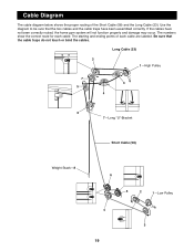
The numbers show the correct route for each cable are labeled. Long Cable (23) 2 1ÑHigh Pulley 7 3 5 4 6 7ÑLong ÒUÓ-Bracket Short Cable (58) Weight StackÑ8 6 5 2 1ÑLow Pulley 4 3 19 Use the diagram to be sure that the cable traps do not touch or bind the cables. The starting ...
The numbers show the correct route for each cable are labeled. Long Cable (23) 2 1ÑHigh Pulley 7 3 5 4 6 7ÑLong ÒUÓ-Bracket Short Cable (58) Weight StackÑ8 6 5 2 1ÑLow Pulley 4 3 19 Use the diagram to be sure that the cable traps do not touch or bind the cables. The starting ...
English Manual
Page 23
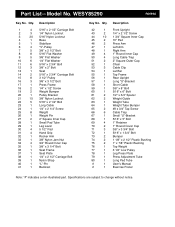
...Rear Upright Long ÒUÓ-Bracket Short Cable 3/8Ó x 8Ó Bolt 5/16Ó x 6Ó Bolt 1/2Ó x 3/4Ó Spacer Weight Guide Weight Tube Weight Tube Bumper #8 x 3/4Ó Tap Screw Cable Trap Small ÒUÓ-Bracket 5/16Ó x 5Ó Bolt 1Ó Retainer 1Ó ...3 3/4Ó Bolt 5/16Ó x 1 3/4Ó Bolt Bumper 1 1/8Ó x 2 1/2Ó Plastic Bushing 1Ó x 7/8Ó Plastic Bushing Top Weight 3 1/2Ó Low Pulley Leg Press Plate Press Adjustment Tube Long Pad Tube UserÕs Manual Exercise Poster Note: Ò#Ó indicates a non-illustrated part.
...Rear Upright Long ÒUÓ-Bracket Short Cable 3/8Ó x 8Ó Bolt 5/16Ó x 6Ó Bolt 1/2Ó x 3/4Ó Spacer Weight Guide Weight Tube Weight Tube Bumper #8 x 3/4Ó Tap Screw Cable Trap Small ÒUÓ-Bracket 5/16Ó x 5Ó Bolt 1Ó Retainer 1Ó ...3 3/4Ó Bolt 5/16Ó x 1 3/4Ó Bolt Bumper 1 1/8Ó x 2 1/2Ó Plastic Bushing 1Ó x 7/8Ó Plastic Bushing Top Weight 3 1/2Ó Low Pulley Leg Press Plate Press Adjustment Tube Long Pad Tube UserÕs Manual Exercise Poster Note: Ò#Ó indicates a non-illustrated part.


