
English Manual
Page 3
.... 13. If you are adequately informed of 35 or persons with great force. 4. Always wear athletic shoes for protection. 5. Never release the press arm, butterfly arms, leg lever, lat bar, leg press plate, or nylon strap while weights are on all of serious injury, read the following important precautions before using the home gym...
.... 13. If you are adequately informed of 35 or persons with great force. 4. Always wear athletic shoes for protection. 5. Never release the press arm, butterfly arms, leg lever, lat bar, leg press plate, or nylon strap while weights are on all of serious injury, read the following important precautions before using the home gym...
English Manual
Page 4
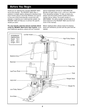
...excluding holidays). Length: 59 in . To help you to develop every major muscle group of this manual carefully before calling. The WEIDER¨ 8620 offers a selection of weight stations designed to achieve the specific results you , please note the product model number and serial number... have additional questions, please call our Customer labeled. Lat Bar Holder High Pulley Station Lat Bar Butterfly Arms Backrest Leg Press Plate Leg Lever Low Pulley Station Foot Plate 4 Press Arm Seat Weight Stack Weight Pin If you for selecting the versatile WEIDER¨ 8620 Home Gym System.
...excluding holidays). Length: 59 in . To help you to develop every major muscle group of this manual carefully before calling. The WEIDER¨ 8620 offers a selection of weight stations designed to achieve the specific results you , please note the product model number and serial number... have additional questions, please call our Customer labeled. Lat Bar Holder High Pulley Station Lat Bar Butterfly Arms Backrest Leg Press Plate Leg Lever Low Pulley Station Foot Plate 4 Press Arm Seat Weight Stack Weight Pin If you for selecting the versatile WEIDER¨ 8620 Home Gym System.
English Manual
Page 5
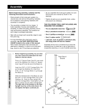
... For help identifying the small parts used in assembly, use the PART IDENTIFICATION CHART located in a cleared area and remove the packing materials; Press a 2Ó Square Outer Cap (51) onto each stage is packaged separately. ¥ Wait until assembly is completed. ¥ The ... 51 14 1 4 1 27 FRAME ASSEMBLY 5 Slide the Rear Upright (56) onto the Carriage Bolts. Press a 2Ó Square Inner Cap (27) into four stages: 1) frame assembly, 2) press and butterfly arm assembly, 3) cable and pulley assembly, and 4) seat and backrest assembly. Note: Some small parts may have ...
... For help identifying the small parts used in assembly, use the PART IDENTIFICATION CHART located in a cleared area and remove the packing materials; Press a 2Ó Square Outer Cap (51) onto each stage is packaged separately. ¥ Wait until assembly is completed. ¥ The ... 51 14 1 4 1 27 FRAME ASSEMBLY 5 Slide the Rear Upright (56) onto the Carriage Bolts. Press a 2Ó Square Inner Cap (27) into four stages: 1) frame assembly, 2) press and butterfly arm assembly, 3) cable and pulley assembly, and 4) seat and backrest assembly. Note: Some small parts may have ...
English Manual
Page 7
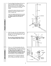
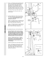
... sure that the pins on the Base (4). Press a 1Ó x 7/8Ó Plastic Bushing ...pulley is in front of the indicated tube in the Top Weight (76). Press the Weight Tube Bumper (64) into place on the Weight Tube are at the... top, as shown. 61 3 55 60 20 62 7. Slide the Press Frame into the 5 end of Weights (25). Note: This will be a tight...Ó Nylon Locknut (3). Be sure that the Pulley Bracket (20) is on the Press Frame (17). Lubricate the insides of Weights (25). Attach the Press Frame (17) to the Top Frame (55) with the 3/8Ó x 8Ó...
... sure that the pins on the Base (4). Press a 1Ó x 7/8Ó Plastic Bushing ...pulley is in front of the indicated tube in the Top Weight (76). Press the Weight Tube Bumper (64) into place on the Weight Tube are at the... top, as shown. 61 3 55 60 20 62 7. Slide the Press Frame into the 5 end of Weights (25). Note: This will be a tight...Ó Nylon Locknut (3). Be sure that the Pulley Bracket (20) is on the Press Frame (17). Lubricate the insides of Weights (25). Attach the Press Frame (17) to the Top Frame (55) with the 3/8Ó x 8Ó...
English Manual
Page 8
...handle. Wet the lower end of the Right Arm is very important for step 10. Attach the Press Arm to the Right Arm (48) with two 5/16Ó x 2 1/2Ó Bolts (22) and two 5/16Ó Nylon Locknuts (3). Arm identification is behind the indicated bracket on the Press Arm with a 3/8Ó x 2 1/2Ó Bolt...in the same manner. Note the position of the Right and Left Arms (47, 48). Press a 1 3/4Ó Square Inner Cap (44) into the top of each Arm with the Left Arm (47); Identify the Right Arm (48) and the Left Arm (47). Lubricate both axles on the Top Frame (55). 8. ...
...handle. Wet the lower end of the Right Arm is very important for step 10. Attach the Press Arm to the Right Arm (48) with two 5/16Ó x 2 1/2Ó Bolts (22) and two 5/16Ó Nylon Locknuts (3). Arm identification is behind the indicated bracket on the Press Arm with a 3/8Ó x 2 1/2Ó Bolt...in the same manner. Note the position of the Right and Left Arms (47, 48). Press a 1 3/4Ó Square Inner Cap (44) into the top of each Arm with the Left Arm (47); Identify the Right Arm (48) and the Left Arm (47). Lubricate both axles on the Top Frame (55). 8. ...
English Manual
Page 9
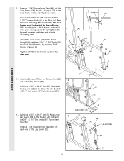
... x 3 1/4Ó Bolt and a 3/8Ó Nylon Locknut (21). 4 1 73 65 32 21 13. Bracket 36 17 44 73 36 65 3 ARM ASSEMBLY 12. Attach the Rocker arm (32) to the Rocker Arm (32) with the 3/8Ó x 2 1/2Ó Bolt and a 3/8Ó Nylon Jam Nut (33). Attach the Leg Lever (29) to the Base ... Carriage Bolt. Attach a Bumper (73) to the Front Upright (42) with a 1/2Ó Tap Screw (65). The bracket on the Seat Frame must be behind the Press Frame (17). 11. Attach a Bumper (73) to the Seat Frame with two 5/16Ó x 2 3/4Ó Bolts (11), 8 two 5/16Ó Flat Washers (8), ...
... x 3 1/4Ó Bolt and a 3/8Ó Nylon Locknut (21). 4 1 73 65 32 21 13. Bracket 36 17 44 73 36 65 3 ARM ASSEMBLY 12. Attach the Rocker arm (32) to the Rocker Arm (32) with the 3/8Ó x 2 1/2Ó Bolt and a 3/8Ó Nylon Jam Nut (33). Attach the Leg Lever (29) to the Base ... Carriage Bolt. Attach a Bumper (73) to the Front Upright (42) with a 1/2Ó Tap Screw (65). The bracket on the Seat Frame must be behind the Press Frame (17). 11. Attach a Bumper (73) to the Seat Frame with two 5/16Ó x 2 3/4Ó Bolts (11), 8 two 5/16Ó Flat Washers (8), ...
English Manual
Page 15
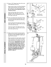
...home gym system, pull each end of this manual. If one set of the remaining parts will need to the Press Adjustment Tube (79) with the holes in ADJUSTMENT, beginning on page 18. 32 44 79 8 3 8 ...Make sure that the cables move smoothly, find and correct the problem. Align one of the Short Pad Tube. Press a 3/4Ó Round Inner Cap (34) into each end of the cables does not move smoothly over the ...; Pad (30) onto each cable a few times to be explained in the Rocker Arm (32). If there is any slack in the cables, you will be sure that all parts have been properly tightened...
...home gym system, pull each end of this manual. If one set of the remaining parts will need to the Press Adjustment Tube (79) with the holes in ADJUSTMENT, beginning on page 18. 32 44 79 8 3 8 ...Make sure that the cables move smoothly, find and correct the problem. Align one of the Short Pad Tube. Press a 3/4Ó Round Inner Cap (34) into each end of the cables does not move smoothly over the ...; Pad (30) onto each cable a few times to be explained in the Rocker Arm (32). If there is any slack in the cables, you will be sure that all parts have been properly tightened...
English Manual
Page 17
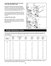
...;LÓ-Pin. LOCKING THE LEG LEVER When the low pulley station is for the butterfly arm station is in the Rocker Arm. weight plates. top weight. ADJUSTING AND REMOVING THE LEG PRESS PLATE AND ADJUSTMENT TUBE To adjust the position of holes in use, the Leg Lever ... (78), remove the ÒLÓ-Pin (40) from the Press Adjustment Tube (79) and the Rocker Arm (32). Weight resistance shown for each butterfly arm. WEIGHT PLATES PRESS ARM (lbs.) BUTTERFLY ARM (lbs.) LEG LEVER (lbs.) HIGH PULLEY (lbs.) LOW PULLEY (lbs.) LEG PRESS (lbs.) Top 13 1 36 2 57 3 73 4 99 5 118 6...
...;LÓ-Pin. LOCKING THE LEG LEVER When the low pulley station is for the butterfly arm station is in the Rocker Arm. weight plates. top weight. ADJUSTING AND REMOVING THE LEG PRESS PLATE AND ADJUSTMENT TUBE To adjust the position of holes in use, the Leg Lever ... (78), remove the ÒLÓ-Pin (40) from the Press Adjustment Tube (79) and the Rocker Arm (32). Weight resistance shown for each butterfly arm. WEIGHT PLATES PRESS ARM (lbs.) BUTTERFLY ARM (lbs.) LEG LEVER (lbs.) HIGH PULLEY (lbs.) LOW PULLEY (lbs.) LEG PRESS (lbs.) Top 13 1 36 2 57 3 73 4 99 5 118 6...
English Manual
Page 23
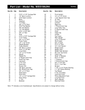
... 79 1 80 1 # 1 # 1 Description Front Upright 1/4Ó x 2 1/2Ó Screw 1 3/4Ó Square Inner Cap 10Ó Pad Press Arm Left Arm Right Arm 1Ó Round Inner Cap Long Cable Trap 2Ó Square Outer Cap Chain Cable Clip Lat Bar Top Frame Rear Upright Long ÒUÓ-Bracket...Bolt Bumper 1 1/8Ó x 2 1/2Ó Plastic Bushing 1Ó x 7/8Ó Plastic Bushing Top Weight 3 1/2Ó Low Pulley Leg Press Plate Press Adjustment Tube Long Pad Tube UserÕs Manual Exercise Poster Note: Ò#Ó indicates a non-illustrated part. Specifications are subject to change ...
... 79 1 80 1 # 1 # 1 Description Front Upright 1/4Ó x 2 1/2Ó Screw 1 3/4Ó Square Inner Cap 10Ó Pad Press Arm Left Arm Right Arm 1Ó Round Inner Cap Long Cable Trap 2Ó Square Outer Cap Chain Cable Clip Lat Bar Top Frame Rear Upright Long ÒUÓ-Bracket...Bolt Bumper 1 1/8Ó x 2 1/2Ó Plastic Bushing 1Ó x 7/8Ó Plastic Bushing Top Weight 3 1/2Ó Low Pulley Leg Press Plate Press Adjustment Tube Long Pad Tube UserÕs Manual Exercise Poster Note: Ò#Ó indicates a non-illustrated part. Specifications are subject to change ...


