Information Update - System Memory
Page 1
... per channel support up to 24 GB. December 2010 NOTE: Actual memory speed depends on the supported memory configurations listed in the Hardware Owner's Manual at support.dell.com/manuals. Dell PowerEdge R710-Information Update System Memory This document provides latest information on your system configuration such as the processor series, DIMM voltage (low or standard), and system firmware...
... per channel support up to 24 GB. December 2010 NOTE: Actual memory speed depends on the supported memory configurations listed in the Hardware Owner's Manual at support.dell.com/manuals. Dell PowerEdge R710-Information Update System Memory This document provides latest information on your system configuration such as the processor series, DIMM voltage (low or standard), and system firmware...
Information Update - System Memory
Page 2
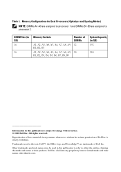
...this text: Dell™, the DELL logo, and PowerEdge™ are assigned to processor 1 and DIMMs B1-B9 are trademarks of Dell Inc. Other trademarks and trade names may be used in this publication is strictly forbidden. All rights reserved. Dell Inc. Memory Configurations for Dual ...Processors (Optimizer and Sparing Modes) NOTE: DIMMs A1-A9 are assigned to processor 2. disclaims any manner whatsoever without notice. © 2010 Dell Inc. is subject to either the entities...
...this text: Dell™, the DELL logo, and PowerEdge™ are assigned to processor 1 and DIMMs B1-B9 are trademarks of Dell Inc. Other trademarks and trade names may be used in this publication is strictly forbidden. All rights reserved. Dell Inc. Memory Configurations for Dual ...Processors (Optimizer and Sparing Modes) NOTE: DIMMs A1-A9 are assigned to processor 2. disclaims any manner whatsoever without notice. © 2010 Dell Inc. is subject to either the entities...
Information Update - Intel Xeon 5600 Series Processors
Page 2
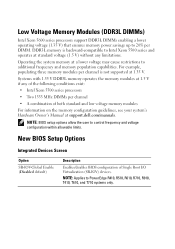
... the user to PowerEdge R410, R510, R610, R710, R910, T410, T610, and T710 systems only. Operating the system memory at 1.35 V. New BIOS Setup Options Integrated Devices Screen Option SR-IOV-Global Enable (Disabled default) Description Enables/disables BIOS configuration of both standard and low voltage memory modules For information on the memory configuration guidelines, see your...
... the user to PowerEdge R410, R510, R610, R710, R910, T410, T610, and T710 systems only. Operating the system memory at 1.35 V. New BIOS Setup Options Integrated Devices Screen Option SR-IOV-Global Enable (Disabled default) Description Enables/disables BIOS configuration of both standard and low voltage memory modules For information on the memory configuration guidelines, see your...
Information Update - Intel Xeon 5600 Series Processors
Page 3
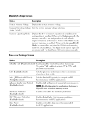
... state to Optimizer mode, the memory controllers run independent of memory operation if a valid memory configuration is enabled. Adjacent Cache Line Prefetch (Enabled default) Enables high utilization of random memory access. Recommended for applications that require high utilization of sequential memory access. Memory Operating Voltage Sets the system memory voltage selection. (Auto Default) Memory Operating Mode Displays the type...
... state to Optimizer mode, the memory controllers run independent of memory operation if a valid memory configuration is enabled. Adjacent Cache Line Prefetch (Enabled default) Enables high utilization of random memory access. Recommended for applications that require high utilization of sequential memory access. Memory Operating Voltage Sets the system memory voltage selection. (Auto Default) Memory Operating Mode Displays the type...
Hardware Owner's Manual
Page 32
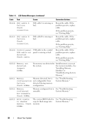
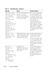
... problem persists, see "Getting Help." Inspect DIMMs. No memory was detected in Install memory or reseat the system. See "Troubleshooting System Memory." Reseat the cable. Error failure. E2012 Memory configured but is unusable. Check DIMMs. Memory configured, but is configuration not configurable. Check cable. See "Installing Memory Modules" or "Troubleshooting System Memory." E2011 Memory Memory detected, but unusable. E1A15 SAS cable B failure. E2010...
... problem persists, see "Getting Help." Inspect DIMMs. No memory was detected in Install memory or reseat the system. See "Troubleshooting System Memory." Reseat the cable. Error failure. E2012 Memory configured but is unusable. Check DIMMs. Memory configured, but is configuration not configurable. Check cable. See "Installing Memory Modules" or "Troubleshooting System Memory." E2011 Memory Memory detected, but unusable. E1A15 SAS cable B failure. E2010...
Hardware Owner's Manual
Page 34
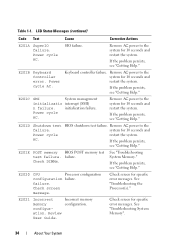
...Remove AC power to the system for 10 seconds and restart the system. E201E POST memory BIOS POST memory test test failure. E2021 Incorrect memory configuration. If the problem persists, see "Getting Help." Power cycle AC. E201D Shutdown ... the problem persists, see "Getting Help." E2020 CPU Processor configuration configuration failure. See "Troubleshooting the Processor(s)." Keyboard controller failure. Table 1-1. initialization failure. Power cycle AC. Incorrect memory configuration. LCD Status Messages (continued) Code Text Cause Corrective Actions ...
...Remove AC power to the system for 10 seconds and restart the system. E201E POST memory BIOS POST memory test test failure. E2021 Incorrect memory configuration. If the problem persists, see "Getting Help." Power cycle AC. E201D Shutdown ... the problem persists, see "Getting Help." E2020 CPU Processor configuration configuration failure. See "Troubleshooting the Processor(s)." Keyboard controller failure. Table 1-1. initialization failure. Power cycle AC. Incorrect memory configuration. LCD Status Messages (continued) Code Text Cause Corrective Actions ...
Hardware Owner's Manual
Page 35
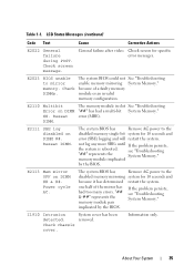
... Intrusion detected. Check screen for 10 seconds and because it has determined restart the system. error (MBE). one half of a faulty memory module or an invalid memory configuration. Check chassis cover. About Your System 35 memory module implicated by the BIOS. Power cycle AC. The system BIOS has Remove AC power to the disabled...
... Intrusion detected. Check screen for 10 seconds and because it has determined restart the system. error (MBE). one half of a faulty memory module or an invalid memory configuration. Check chassis cover. About Your System 35 memory module implicated by the BIOS. Power cycle AC. The system BIOS has Remove AC power to the disabled...
Hardware Owner's Manual
Page 37
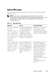
.... Check other messages for a ECC mode was enabled in setting has been disabled. Memory configuration does not support Advanced ECC Memory Mode. See "System Memory." The Advanced ECC be faulty. About Your System 37 For memory configuration information, see "Troubleshooting System Memory." System Messages Message Causes Corrective Actions 128-bit Advanced The Advanced ECC option Check other...
.... Check other messages for a ECC mode was enabled in setting has been disabled. Memory configuration does not support Advanced ECC Memory Mode. See "System Memory." The Advanced ECC be faulty. About Your System 37 For memory configuration information, see "Troubleshooting System Memory." System Messages Message Causes Corrective Actions 128-bit Advanced The Advanced ECC option Check other...

Hardware Owner's Manual
Page 38
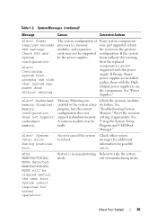
... not support Node Interleaving. The system will run but without warning. Wait for 10 seconds and restart the system. Node Interleaving disabled! For memory configuration information, see "Troubleshooting System Memory." 38 About Your System The iDRAC6 is not responding to BIOS communication either because it is hung. Continuing system boot accepts the risk...
... not support Node Interleaving. The system will run but without warning. Wait for 10 seconds and restart the system. Node Interleaving disabled! For memory configuration information, see "Troubleshooting System Memory." 38 About Your System The iDRAC6 is not responding to BIOS communication either because it is hung. Continuing system boot accepts the risk...
Hardware Owner's Manual
Page 39
... to take the system mode. MANUFACTURING MODE will be supported by the power supplies. The system configuration of manufacturing mode. Memory configuration does not support redundant memory. Memory Mirroring was enabled in manufacturing Reboot to reboot. See "Troubleshooting System Memory." See "Using the System Setup Program and UEFI Boot Manager." Check other system messages for additional...
... to take the system mode. MANUFACTURING MODE will be supported by the power supplies. The system configuration of manufacturing mode. Memory configuration does not support redundant memory. Memory Mirroring was enabled in manufacturing Reboot to reboot. See "Troubleshooting System Memory." See "Using the System Setup Program and UEFI Boot Manager." Check other system messages for additional...
Hardware Owner's Manual
Page 41
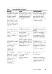
...the mouse or keyboard cable. Use the system setup program to UEFI. Decreasing Faulty or improperly Reseat the memory modules. available memory installed memory modules. The memory module configuration for NIC settings. Ensure that the proper bootable media is loose or improperly connected. Check the system management...match. Error 8602 Auxiliary Device Failure. Mouse or keyboard cable is available. About Your System 41 Invalid memory configuration on each processor must be identical. Ensure that the boot mode is set in management tools. See "Troubleshooting System...
...the mouse or keyboard cable. Use the system setup program to UEFI. Decreasing Faulty or improperly Reseat the memory modules. available memory installed memory modules. The memory module configuration for NIC settings. Ensure that the proper bootable media is loose or improperly connected. Check the system management...match. Error 8602 Auxiliary Device Failure. Mouse or keyboard cable is available. About Your System 41 Invalid memory configuration on each processor must be identical. Ensure that the boot mode is set in management tools. See "Troubleshooting System...
Hardware Owner's Manual
Page 43
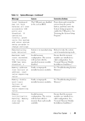
... detected System is physically available. Ensure that the memory modules are disabled. Memory double word logic failure at address, read value expecting value Faulty or improperly See "Troubleshooting System installed memory modules. About Your System 43 The following DIMM has been disabled: x Invalid memory configuration. See "General Memory Module Installation Guidelines." The USB ports are installed...
... detected System is physically available. Ensure that the memory modules are disabled. Memory double word logic failure at address, read value expecting value Faulty or improperly See "Troubleshooting System installed memory modules. About Your System 43 The following DIMM has been disabled: x Invalid memory configuration. See "General Memory Module Installation Guidelines." The USB ports are installed...
Hardware Owner's Manual
Page 44
... was terminated by keystroke. Pairs must be intentionally set to minimum frequency. The BIOS setting has been disabled. See "General Memory Module Installation Guidelines." The memory configuration does not match the setting in size and geometry. Table 1-2. Memory write/read failure at address, read value expecting value Faulty or improperly See "Troubleshooting System installed...
... was terminated by keystroke. Pairs must be intentionally set to minimum frequency. The BIOS setting has been disabled. See "General Memory Module Installation Guidelines." The memory configuration does not match the setting in size and geometry. Table 1-2. Memory write/read failure at address, read value expecting value Faulty or improperly See "Troubleshooting System installed...
Hardware Owner's Manual
Page 46
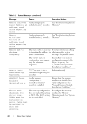
... Message Causes Corrective Actions Plug & Play Configuration Error Error encountered in the clear position (pins 1 and 3) and reboot the system. If the problem persists, see "Troubleshooting Expansion Cards." See "General Memory Module Installation Guidelines." not found The operating...USB, or SATA particular sector on the disk, cables are installed in socket. Invalid memory configuration. Quad rank DIMM detected after single rank or dual rank DIMM in a valid configuration. "Troubleshooting a USB Device," "Troubleshooting an Optical Drive," or "Troubleshooting a Hard ...
... Message Causes Corrective Actions Plug & Play Configuration Error Error encountered in the clear position (pins 1 and 3) and reboot the system. If the problem persists, see "Troubleshooting Expansion Cards." See "General Memory Module Installation Guidelines." not found The operating...USB, or SATA particular sector on the disk, cables are installed in socket. Invalid memory configuration. Quad rank DIMM detected after single rank or dual rank DIMM in a valid configuration. "Troubleshooting a USB Device," "Troubleshooting an Optical Drive," or "Troubleshooting a Hard ...
Hardware Owner's Manual
Page 48
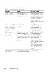
... DIMMs should match in geometry: x,x,... faulty system SETUP program battery. Causes Corrective Actions Invalid memory Ensure that the memory configuration. The following DIMMs should match in See "System Memory." not detected on x thermal sensor is installed in size: x,x,... Time-of data Installation ..., replace the system battery. The following DIMMs should match in a memory modules do not valid configuration. please run settings; The following DIMMs should match in size, number of "General Memory Module ranks, or number of -day not Incorrect Time or Date ...
... DIMMs should match in geometry: x,x,... faulty system SETUP program battery. Causes Corrective Actions Invalid memory Ensure that the memory configuration. The following DIMMs should match in See "System Memory." not detected on x thermal sensor is installed in size: x,x,... Time-of data Installation ..., replace the system battery. The following DIMMs should match in a memory modules do not valid configuration. please run settings; The following DIMMs should match in size, number of "General Memory Module ranks, or number of -day not Incorrect Time or Date ...

Hardware Owner's Manual
Page 50
See the Unified Server Configuration user documentation for instructions on corrupted. support.dell.com. See "Troubleshooting System Memory." Ensure that the memory modules are installed in protected mode Improperly seated memory modules or faulty keyboard/mouse controller chip. Invalid memory configuration. Memory modules are installed in the system firmware or has been lost due to system board replacement. Unexpected...
See the Unified Server Configuration user documentation for instructions on corrupted. support.dell.com. See "Troubleshooting System Memory." Ensure that the memory modules are installed in protected mode Improperly seated memory modules or faulty keyboard/mouse controller chip. Invalid memory configuration. Memory modules are installed in the system firmware or has been lost due to system board replacement. Unexpected...
Hardware Owner's Manual
Page 51
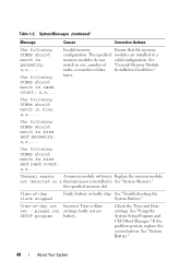
... "Getting Help." DIMM's not optimal for any faulty components specified in the Advanced ECC Memory Advanced ECC Memory following slot Mode. reboot. during the error. About Your System 51 System Messages (continued) Message Causes Corrective Actions Unused memory The memory configuration is not Install the control panel, or installed or has a faulty cable check the...
... "Getting Help." DIMM's not optimal for any faulty components specified in the Advanced ECC Memory Advanced ECC Memory following slot Mode. reboot. during the error. About Your System 51 System Messages (continued) Message Causes Corrective Actions Unused memory The memory configuration is not Install the control panel, or installed or has a faulty cable check the...
Hardware Owner's Manual
Page 52
... Energy Smart power two Energy Smart power supply are installed, replace them with this warning, configuration. You can also run but with reduced functionality. Unsupported memory configuration detected. If the system system by the power supplies. If Energy Smart power supplies are...minimum frequencies to the previous Check PSU and cards may not be supported configuration. See "Power Supplies." The recommended memory configuration is not optimal. If the problem persists, see "Troubleshooting System Memory." 52 About Your System modules, and expansion the system to meet PSU...
... Energy Smart power two Energy Smart power supply are installed, replace them with this warning, configuration. You can also run but with reduced functionality. Unsupported memory configuration detected. If the system system by the power supplies. If Energy Smart power supplies are...minimum frequencies to the previous Check PSU and cards may not be supported configuration. See "Power Supplies." The recommended memory configuration is not optimal. If the problem persists, see "Troubleshooting System Memory." 52 About Your System modules, and expansion the system to meet PSU...

Hardware Owner's Manual
Page 59
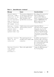
... running multi-bit advanced ECC. CAUTION: When setting this field is Enabled, memory interleaving is supported if a symmetric memory configuration is installed. For information about the memory modes, see "System Memory." System Memory Type Displays the type of system memory. System Memory Testing Specifies whether system memory tests are Enabled and Disabled. When set to enter the System Setup...
... running multi-bit advanced ECC. CAUTION: When setting this field is Enabled, memory interleaving is supported if a symmetric memory configuration is installed. For information about the memory modes, see "System Memory." System Memory Type Displays the type of system memory. System Memory Testing Specifies whether system memory tests are Enabled and Disabled. When set to enter the System Setup...
Hardware Owner's Manual
Page 129
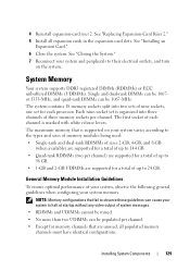
...total of system messages. • RDIMMs and UDIMMs cannot be mixed. • No more than two UDIMMs can be 1067-MHz. NOTE: Memory configurations that is organized into two sets of up to 144 GB. • Quad-rank RDIMMs (two per channel) are supported for a total of... nine sockets, one set is supported on the system. See "Replacing Expansion-Card Riser 2." 5 Install all populated memory channels must have identical configurations. General Memory Module Installation Guidelines To ensure optimal performance of your system, observe the following general guidelines when...
...total of system messages. • RDIMMs and UDIMMs cannot be mixed. • No more than two UDIMMs can be 1067-MHz. NOTE: Memory configurations that is organized into two sets of up to 144 GB. • Quad-rank RDIMMs (two per channel) are supported for a total of... nine sockets, one set is supported on the system. See "Replacing Expansion-Card Riser 2." 5 Install all populated memory channels must have identical configurations. General Memory Module Installation Guidelines To ensure optimal performance of your system, observe the following general guidelines when...


