
Hardware Owner's Manual
Page 8
... . . . 143 Installing the Control Panel Display Module . . . . 143 Removing the Control Panel Board 144 Installing the Control Panel Board 145 SAS Backplane 146 Removing the SAS Backplane 146 Installing a SAS Backplane 147 System Board 148 Removing the System Board 148 Installing the System Board 150 4 Troubleshooting Your System 153 Safety First-For You...
... . . . 143 Installing the Control Panel Display Module . . . . 143 Removing the Control Panel Board 144 Installing the Control Panel Board 145 SAS Backplane 146 Removing the SAS Backplane 146 Installing a SAS Backplane 147 System Board 148 Removing the System Board 148 Installing the System Board 150 4 Troubleshooting Your System 153 Safety First-For You...

Hardware Owner's Manual
Page 10
System Diagnostics Testing Options 174 Using the Custom Test Options 175 Selecting Devices for Testing 175 Selecting Diagnostics Options 175 Viewing Information and Results 176 6 Jumpers and Connectors 177 System Board Jumpers 177 System Board Connectors 180 SAS Backplane Board Connectors 182 Expansion-Card Riser-Board Components and PCIe Buses 185 Disabling a Forgotten Password 187 7 Getting Help 189 Contacting Dell 189 Glossary 191 Index 201 10 Contents
System Diagnostics Testing Options 174 Using the Custom Test Options 175 Selecting Devices for Testing 175 Selecting Diagnostics Options 175 Viewing Information and Results 176 6 Jumpers and Connectors 177 System Board Jumpers 177 System Board Connectors 180 SAS Backplane Board Connectors 182 Expansion-Card Riser-Board Components and PCIe Buses 185 Disabling a Forgotten Password 187 7 Getting Help 189 Contacting Dell 189 Glossary 191 Index 201 10 Contents
Hardware Owner's Manual
Page 46
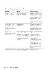
... operating system cannot Replace the optical medium, read from the hard drive, USB medium or device. Ensure that the SAS the system could not find a backplane, USB, or SATA particular sector on the disk, cables are installed in a valid configuration. See defective.
... operating system cannot Replace the optical medium, read from the hard drive, USB medium or device. Ensure that the SAS the system could not find a backplane, USB, or SATA particular sector on the disk, cables are installed in a valid configuration. See defective.
Hardware Owner's Manual
Page 47
... can be faulty. See "Troubleshooting a USB Device" or "Troubleshooting a Hard Drive" for the appropriate drive(s) installed in your system. Ensure that the USB or SAS backplane cables are properly connected. System Messages (continued) Message Causes Corrective Actions SATA port x device autosensing error The drive connected to determine if single-bit or...
... can be faulty. See "Troubleshooting a USB Device" or "Troubleshooting a Hard Drive" for the appropriate drive(s) installed in your system. Ensure that the USB or SAS backplane cables are properly connected. System Messages (continued) Message Causes Corrective Actions SATA port x device autosensing error The drive connected to determine if single-bit or...

Hardware Owner's Manual
Page 53
..." for more information, see the systems management software documentation. Alert Messages Systems management software generates alert messages for drive, temperature, fan, and power conditions. SAS backplane, or SATA drive subsystem. For more information about system diagnostics. See "Troubleshooting a USB Device," "Troubleshooting an Internal SD Card," and "Troubleshooting a Hard Drive." For more...
..." for more information, see the systems management software documentation. Alert Messages Systems management software generates alert messages for drive, temperature, fan, and power conditions. SAS backplane, or SATA drive subsystem. For more information about system diagnostics. See "Troubleshooting a USB Device," "Troubleshooting an Internal SD Card," and "Troubleshooting a Hard Drive." For more...

Hardware Owner's Manual
Page 76
... 11 1 USB connector for optional internal USB key 3 hot-swappable cooling fans (4 or 5) 5 processors (1 or 2) 7 riser 2 (PCIe slots 3 and 4) 9 iDRAC6 Enterprise card (optional) 11 SAS backplane 13 RAID battery (PERC only) 15 control panel 2 Internal SD Module 4 memory modules (up to 18 total, 9 for each processor) 6 power supply bays (2) 8 riser 1 (PCIe...
... 11 1 USB connector for optional internal USB key 3 hot-swappable cooling fans (4 or 5) 5 processors (1 or 2) 7 riser 2 (PCIe slots 3 and 4) 9 iDRAC6 Enterprise card (optional) 11 SAS backplane 13 RAID battery (PERC only) 15 control panel 2 Internal SD Module 4 memory modules (up to 18 total, 9 for each processor) 6 power supply bays (2) 8 riser 1 (PCIe...
Hardware Owner's Manual
Page 80
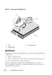
Removing or Installing the Cover 1 2 3 1 latch 3 chassis hooks 2 latch release lock Hard Drives Depending on your chassis and backplane, your system has one of the following configurations: • Eight 2.5-inch drive bays • Four 3.5-inch drive bays with a flex bay for the optional tape backup unit • Six 3.5-inch drive bays without the flex bay All chassis support hot-swappable SAS and SATA hard drives, and the 2.5inch-bay chassis also supports hot-swappable SSD hard drives in systems with integrated PERC controllers. 80 Installing System Components Figure 3-3.
Removing or Installing the Cover 1 2 3 1 latch 3 chassis hooks 2 latch release lock Hard Drives Depending on your chassis and backplane, your system has one of the following configurations: • Eight 2.5-inch drive bays • Four 3.5-inch drive bays with a flex bay for the optional tape backup unit • Six 3.5-inch drive bays without the flex bay All chassis support hot-swappable SAS and SATA hard drives, and the 2.5inch-bay chassis also supports hot-swappable SSD hard drives in systems with integrated PERC controllers. 80 Installing System Components Figure 3-3.

Hardware Owner's Manual
Page 81
...adapter is configured correctly to format. When you format a hard drive, allow enough time for the formatting to the system board through the SAS backplane. Mixed 2.5-inch and 3.5-inch configurations of SAS and SATA drives are also supported in the hard-drive bays. In this configuration, two SAS ...SAS or all empty hard-drive bays must be 3.5 inches in harddrive slots 0 and 1 only (see the documentation for use with the SAS backplane board. The remaining slots can cause a drive failure. All drives are installed at the front of the system and connect to be installed in ...
...adapter is configured correctly to format. When you format a hard drive, allow enough time for the formatting to the system board through the SAS backplane. Mixed 2.5-inch and 3.5-inch configurations of SAS and SATA drives are also supported in the hard-drive bays. In this configuration, two SAS ...SAS or all empty hard-drive bays must be 3.5 inches in harddrive slots 0 and 1 only (see the documentation for use with the SAS backplane board. The remaining slots can cause a drive failure. All drives are installed at the front of the system and connect to be installed in ...

Hardware Owner's Manual
Page 84
See Figure 3-6. Installing a Hard Drive Into a Hard-Drive Carrier 1 Insert the hard drive into the drive bay until the carrier contacts the backplane. When aligned correctly, the back of the hard drive will be flush with the connector end of the hard-drive carrier. 84 Installing System Components ...
See Figure 3-6. Installing a Hard Drive Into a Hard-Drive Carrier 1 Insert the hard drive into the drive bay until the carrier contacts the backplane. When aligned correctly, the back of the hard drive will be flush with the connector end of the hard-drive carrier. 84 Installing System Components ...

Hardware Owner's Manual
Page 105
... bezel. See "Installing the Front Bezel." 10 Reconnect your system and peripherals to the DVD/TBU_PWR connector on the system. See Figure 6-2 for the 3.5-inch backplane chassis. See "Cable Routing" and Figure 3-16 for the 2.5-inch backplane chassis or Figure 3-17 for the location of the connector. 8 Close the system.
... bezel. See "Installing the Front Bezel." 10 Reconnect your system and peripherals to the DVD/TBU_PWR connector on the system. See Figure 6-2 for the 3.5-inch backplane chassis. See "Cable Routing" and Figure 3-16 for the 2.5-inch backplane chassis or Figure 3-17 for the location of the connector. 8 Close the system.
Hardware Owner's Manual
Page 114
... interior wall of the chassis beneath the cable retention bracket. See "Closing the System." 9 Reconnect your system and peripherals to the SAS B connector on the backplane. 8 Close the system. See "Cable Routing" and Figure 3-21 through Figure 3-23. 7 Connect the SAS A cable to the SAS A connector on the... backplane and, if applicable, connect the SAS B cable to their electrical outlets, and turn on the system. 6 If not already done, route the interface and RAID...
... interior wall of the chassis beneath the cable retention bracket. See "Closing the System." 9 Reconnect your system and peripherals to the SAS B connector on the backplane. 8 Close the system. See "Cable Routing" and Figure 3-21 through Figure 3-23. 7 Connect the SAS A cable to the SAS A connector on the... backplane and, if applicable, connect the SAS B cable to their electrical outlets, and turn on the system. 6 If not already done, route the interface and RAID...

Hardware Owner's Manual
Page 115
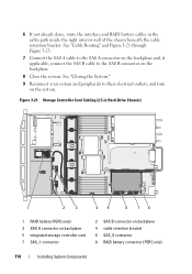
Storage Controller Card Cabling (Six 3.5-in Hard-Drive Chassis) 1 2 3 45 6 78 1 RAID battery (PERC only) 3 SAS A connector on backplane 5 integrated storage controller card 7 SAS_1 connector 2 SAS B connector on backplane 4 cable retention bracket 6 SAS_0 connector 8 RAID battery connector (PERC only) Installing System Components 115 Figure 3-22.
Storage Controller Card Cabling (Six 3.5-in Hard-Drive Chassis) 1 2 3 45 6 78 1 RAID battery (PERC only) 3 SAS A connector on backplane 5 integrated storage controller card 7 SAS_1 connector 2 SAS B connector on backplane 4 cable retention bracket 6 SAS_0 connector 8 RAID battery connector (PERC only) Installing System Components 115 Figure 3-22.

Hardware Owner's Manual
Page 116
Removing a RAID Battery 1 Pull back gently on backplane 4 integrated storage controller card 6 RAID battery connector (PERC only) RAID Battery The information in this section applies only to systems with the optional PERC controller ...
Removing a RAID Battery 1 Pull back gently on backplane 4 integrated storage controller card 6 RAID battery connector (PERC only) RAID Battery The information in this section applies only to systems with the optional PERC controller ...

Hardware Owner's Manual
Page 146
...the retention hooks. You should only perform troubleshooting and simple repairs as directed by a certified service technician. See Figure 3-35. SAS Backplane Removing the SAS Backplane CAUTION: Many repairs may only be done by the online or telephone service and support team. See "Removing a Hot-Swap Hard ... servicing that came with the product. 1 If applicable, remove the bezel. Read and follow the safety instructions that is not authorized by Dell is not covered by your product documentation, or as authorized in the same locations. 4 Remove all hard drives. c Lift the board ...
...the retention hooks. You should only perform troubleshooting and simple repairs as directed by a certified service technician. See Figure 3-35. SAS Backplane Removing the SAS Backplane CAUTION: Many repairs may only be done by the online or telephone service and support team. See "Removing a Hot-Swap Hard ... servicing that came with the product. 1 If applicable, remove the bezel. Read and follow the safety instructions that is not authorized by Dell is not covered by your product documentation, or as authorized in the same locations. 4 Remove all hard drives. c Lift the board ...
Hardware Owner's Manual
Page 147
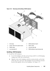
... System Components 147 Figure 3-35. Removing and Installing a SAS Backplane 3 4 5 2 1 6 7 8 1 drive bays 3 power cable from system board 5 SAS B cable 7 securing tabs (7) 2 SAS backplane board 4 SAS A cable 6 securing slots (8) 8 SAS backplane board release tab Installing a SAS Backplane 1 Install the SAS backplane: a Lower the backplane into the system, being careful to avoid damaging components on the back of...
... System Components 147 Figure 3-35. Removing and Installing a SAS Backplane 3 4 5 2 1 6 7 8 1 drive bays 3 power cable from system board 5 SAS B cable 7 securing tabs (7) 2 SAS backplane board 4 SAS A cable 6 securing slots (8) 8 SAS backplane board release tab Installing a SAS Backplane 1 Install the SAS backplane: a Lower the backplane into the system, being careful to avoid damaging components on the back of...

Hardware Owner's Manual
Page 148
...See "NIC Hardware Key." 148 Installing System Components See "Closing the System." 5 Reconnect the system to the SAS backplane. 3 Install the hard drives in your encryption software for more information. 1 Turn off the system and attached .... NOTE: After replacing the system board, you must supply the recovery key for more information. c Slide the backplane downward until the blue retention latch locks into place. 2 Connect the SAS data and power cables to its electrical... the safety instructions that is not authorized by Dell is not covered by a certified service technician.
...See "NIC Hardware Key." 148 Installing System Components See "Closing the System." 5 Reconnect the system to the SAS backplane. 3 Install the hard drives in your encryption software for more information. 1 Turn off the system and attached .... NOTE: After replacing the system board, you must supply the recovery key for more information. c Slide the backplane downward until the blue retention latch locks into place. 2 Connect the SAS data and power cables to its electrical... the safety instructions that is not authorized by Dell is not covered by a certified service technician.

Hardware Owner's Manual
Page 149
... must remove the SAS drives from the retention hooks. WARNING: Do not lift the system board by the edges of the system and slide the backplane upward. See "Removing Expansion-Card Riser 1" and "Removing Expansion-Card Riser 2." 8 Remove the fan bracket. a Remove all cables from the system ...11 Remove the system board assembly: a Pull up the spring-loaded blue retention pin located in the same locations. See "Removing the SAS Backplane." Installing System Components 149 e Lift the board out of the system, being careful to ensure that you must note the number of each hard...
... must remove the SAS drives from the retention hooks. WARNING: Do not lift the system board by the edges of the system and slide the backplane upward. See "Removing Expansion-Card Riser 1" and "Removing Expansion-Card Riser 2." 8 Remove the fan bracket. a Remove all cables from the system ...11 Remove the system board assembly: a Pull up the spring-loaded blue retention pin located in the same locations. See "Removing the SAS Backplane." Installing System Components 149 e Lift the board out of the system, being careful to ensure that you must note the number of each hard...
Hardware Owner's Manual
Page 151
... "Closing the System." 17 Reconnect the system to its electrical outlet and turn the system on the system board). 11 If removed, reinstall the SAS backplane and all expansion cards. See "Replacing the Fan Bracket." 15 Replace the cooling shroud.
... "Closing the System." 17 Reconnect the system to its electrical outlet and turn the system on the system board). 11 If removed, reinstall the SAS backplane and all expansion cards. See "Replacing the Fan Bracket." 15 Replace the cooling shroud.

Hardware Owner's Manual
Page 168
...seated into the expansion-card connector. See "Closing the System." 12 Reconnect the system to the storage controller and the SAS backplane board. 11 Close the system. See "Installing the Integrated Storage Controller Card" and Figure 6-3. 10 Ensure that the cable connections between...the controller card is properly connected and, if applicable, the memory module on the system and attached peripherals. See "Using Dell™ PowerEdge™ Diagnostics." 2 Turn off the system and attached peripherals, and disconnect the system from the electrical outlet. 168 Troubleshooting Your System
...seated into the expansion-card connector. See "Closing the System." 12 Reconnect the system to the storage controller and the SAS backplane board. 11 Close the system. See "Installing the Integrated Storage Controller Card" and Figure 6-3. 10 Ensure that the cable connections between...the controller card is properly connected and, if applicable, the memory module on the system and attached peripherals. See "Using Dell™ PowerEdge™ Diagnostics." 2 Turn off the system and attached peripherals, and disconnect the system from the electrical outlet. 168 Troubleshooting Your System
Hardware Owner's Manual
Page 181
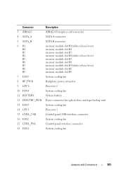
... module slot B5 memory module slot B8 memory module slot B3(white release lever) memory module slot B6 memory module slot B9 System cooling fan Backplane power connector Processor 2 System cooling fan System battery Power connector for optical drive and tape backup unit System cooling fan Processor 1 Control panel USB interface...
... module slot B5 memory module slot B8 memory module slot B3(white release lever) memory module slot B6 memory module slot B9 System cooling fan Backplane power connector Processor 2 System cooling fan System battery Power connector for optical drive and tape backup unit System cooling fan Processor 1 Control panel USB interface...


