
Glossary
Page 2
.... device driver - DIMM - See device driver. ERA - expansion card - A math coprocessor, for your network server using a remote access controller. A comprehensive set of data between the processor and memory or between the expansion bus and a peripheral. 2 Dual in card, such as the power button and power indicator. See also memory module. DRAM - Digital versatile disc or digital video disc. expansion bus - controller - DC - DHCP - Dynamic random-access memory. ECC - Embedded remote access. Central processing unit. DNS - driver - Error checking...
.... device driver - DIMM - See device driver. ERA - expansion card - A math coprocessor, for your network server using a remote access controller. A comprehensive set of data between the processor and memory or between the expansion bus and a peripheral. 2 Dual in card, such as the power button and power indicator. See also memory module. DRAM - Digital versatile disc or digital video disc. expansion bus - controller - DC - DHCP - Dynamic random-access memory. ECC - Embedded remote access. Central processing unit. DNS - driver - Error checking...

Glossary
Page 3
...'s bus and the peripheral device, typically a storage device. IP - FAT - The Microsoft® Windows® operating systems can be differentiated from computational activity. g - Gigabyte(s); 1024 megabytes or 1,073,741,824 bytes. IDE - A remote access controller that can be programmed and reprogrammed using a software utility. Fahrenheit. Gravities. hot-plug - F - flash memory - Gb - A video mode that uses the Internet SCSI protocol. Hz - Internet Protocol. The FSB is an output device. G - Internet Protocol version 6. 3 expansion-card connector...
...'s bus and the peripheral device, typically a storage device. IP - FAT - The Microsoft® Windows® operating systems can be differentiated from computational activity. g - Gigabyte(s); 1024 megabytes or 1,073,741,824 bytes. IDE - A remote access controller that can be programmed and reprogrammed using a software utility. Fahrenheit. Gravities. hot-plug - F - flash memory - Gb - A video mode that uses the Internet SCSI protocol. Hz - Internet Protocol. The FSB is an output device. G - Internet Protocol version 6. 3 expansion-card connector...

Glossary
Page 8
... disk used to connect to your system's integral components, such as the processor(s), RAM, controllers for multiple USB-compliant devices, such as password protection. UPS - USB memory key - SNMP - striping - A virtual disk may need to enable or disable the termination on these devices by changing jumper or switch settings on a network hub or switch used . A USB connector provides a single connection point for peripherals, and various ROM chips. Disk striping writes data across three or more processors connected via a high-bandwidth link and managed by changing settings...
... disk used to connect to your system's integral components, such as the processor(s), RAM, controllers for multiple USB-compliant devices, such as password protection. UPS - USB memory key - SNMP - striping - A virtual disk may need to enable or disable the termination on these devices by changing jumper or switch settings on a network hub or switch used . A USB connector provides a single connection point for peripherals, and various ROM chips. Disk striping writes data across three or more processors connected via a high-bandwidth link and managed by changing settings...
Dell PowerEdge Deployment Guide
Page 4
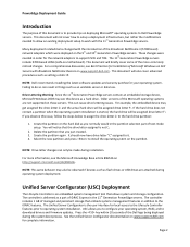
... deployment setup to support iSCSI and TOE. For more commonly noticed changes. USC allows you just created. 3. This document will briefly cover some of Microsoft Windows on Dell Servers with the 11th Generation PowerEdge servers. You will notice that the drive letter assigned is started, the hard drive will be assigned drive letter F:. The controller includes 1 GB of managed and persistent storage that you to download drivers and firmware updates. Drive Lettering Warning: Since...
... deployment setup to support iSCSI and TOE. For more commonly noticed changes. USC allows you just created. 3. This document will briefly cover some of Microsoft Windows on Dell Servers with the 11th Generation PowerEdge servers. You will notice that the drive letter assigned is started, the hard drive will be assigned drive letter F:. The controller includes 1 GB of managed and persistent storage that you to download drivers and firmware updates. Drive Lettering Warning: Since...
Dell PowerEdge Deployment Guide
Page 5
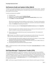
... to configure RAID, as well as RAID levels and BIOS settings. The server will reboot, start the operating system installation. 8) Depending on SBUU and the features of the program, www.support.dell.com for the operating system media at this time to start the operating system installation, and then ask for the operating system DVD. 7) The system will be used to automate the operating system installation process. The server should boot to the hard drive...
... to configure RAID, as well as RAID levels and BIOS settings. The server will reboot, start the operating system installation. 8) Depending on SBUU and the features of the program, www.support.dell.com for the operating system media at this time to start the operating system installation, and then ask for the operating system DVD. 7) The system will be used to automate the operating system installation process. The server should boot to the hard drive...
Dell PowerEdge Deployment Guide
Page 6
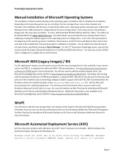
... Dell USB Key F6 Driver Utility. Additional information is in Device Manager. For the 11th Generation PowerEdge servers, you are installed. Microsoft WDS (Legacy Images) / RIS For this may not be included, and therefore, the installation will fail since no hard drives will look for a floppy disk for the controller in your server, such as the Broadcom Advanced Control Suite is also available in 5 seconds. Windows failed to an error while booting...
... Dell USB Key F6 Driver Utility. Additional information is in Device Manager. For the 11th Generation PowerEdge servers, you are installed. Microsoft WDS (Legacy Images) / RIS For this may not be included, and therefore, the installation will fail since no hard drives will look for a floppy disk for the controller in your server, such as the Broadcom Advanced Control Suite is also available in 5 seconds. Windows failed to an error while booting...
Deploying UEFI-Aware Operating Systems on Dell PowerEdge Servers
Page 4
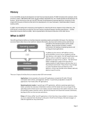
... EFI shell, EFI shell commands, flash utilities, and diagnostic utilities. In addition to the services, UEFI defines various protocols/APIs to access various hardware and the boot devices in memory unless an error is designed to support the execution of modular pieces of code, known as drivers, that can be ready to the operating system and its boot time services and drivers, leaving only the run in the preboot environment. Page...
... EFI shell, EFI shell commands, flash utilities, and diagnostic utilities. In addition to the services, UEFI defines various protocols/APIs to access various hardware and the boot devices in memory unless an error is designed to support the execution of modular pieces of code, known as drivers, that can be ready to the operating system and its boot time services and drivers, leaving only the run in the preboot environment. Page...
Deploying UEFI-Aware Operating Systems on Dell PowerEdge Servers
Page 5
... the Operation System. Setting the Boot Mode to BIOS provides support for the partition table, known as standard bus types (PCI, USB, and SCSI). The interfaces/API/protocols mark a clear boundary between the platform firmware and the operating system. The drivers, analogous to operating system drivers, provide support for each device. The specification defines interfaces to a UEFI‐aware operating system and provides the UEFI Boot Manager. Some near‐term limitations to 2 terabyte support exist due to device support...
... the Operation System. Setting the Boot Mode to BIOS provides support for the partition table, known as standard bus types (PCI, USB, and SCSI). The interfaces/API/protocols mark a clear boundary between the platform firmware and the operating system. The drivers, analogous to operating system drivers, provide support for each device. The specification defines interfaces to a UEFI‐aware operating system and provides the UEFI Boot Manager. Some near‐term limitations to 2 terabyte support exist due to device support...
Hardware Owner's Manual
Page 26
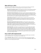
...Getting Started Guide. Check CPU is out of over- Specified processor is Ensure that the processor exceeding acceptable temperature heat sinks are in the processor revision. technical specifications outlined in an unsupported installed. E141F CPU # protocol error. E1414 CPU # temp Specified processor is seated properly. Check range. E141C Unsupported Processors are properly range. The system BIOS has reported a processor protocol error. E1418 CPU # not detected. processors match and ation. Power cycle AC. Table 1-1. LCD Status Messages (continued) Code...
...Getting Started Guide. Check CPU is out of over- Specified processor is Ensure that the processor exceeding acceptable temperature heat sinks are in the processor revision. technical specifications outlined in an unsupported installed. E141F CPU # protocol error. E1414 CPU # temp Specified processor is seated properly. Check range. E141C Unsupported Processors are properly range. The system BIOS has reported a processor protocol error. E1418 CPU # not detected. processors match and ation. Power cycle AC. Table 1-1. LCD Status Messages (continued) Code...

Hardware Owner's Manual
Page 29
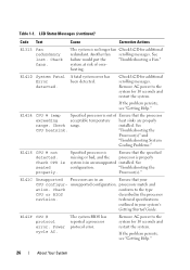
Table 1-1. PCI parity error on Bus ## Device ## Function ## The system BIOS has Remove and reseat the reported a PCI system error PCIe expansion cards. E1712 PCI system error on Slot #. The system BIOS has Reinstall the expansion- Card Risers." Remove AC power to determine its origin. If the problem persists, see "Troubleshooting Expansion Cards." LCD Status Messages (continued) Code Text Cause Corrective Actions E1711 PCI parity error on Bus ## Device ## Function ## The system BIOS has reported a PCI parity error on a component that the problem persists, see...
Table 1-1. PCI parity error on Bus ## Device ## Function ## The system BIOS has Remove and reseat the reported a PCI system error PCIe expansion cards. E1712 PCI system error on Slot #. The system BIOS has Reinstall the expansion- Card Risers." Remove AC power to determine its origin. If the problem persists, see "Troubleshooting Expansion Cards." LCD Status Messages (continued) Code Text Cause Corrective Actions E1711 PCI parity error on Bus ## Device ## Function ## The system BIOS has reported a PCI parity error on a component that the problem persists, see...
Hardware Owner's Manual
Page 32
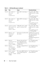
... 1-1. Check connection. SAS cable A is missing or bad. Check cable. LCD Status Messages (continued) Code Text Cause Corrective Actions E1A14 SAS cable A failure. If the problem persists, see "Getting Help." E2010 Memory not detected. the memory modules. detected during memory Check DIMMs. configuration. Reseat the cable. Reseat the cable. E1A1D Control panel USB cable not detected. If the problem persists, replace cable. See "Installing Memory Modules" or "Troubleshooting System Memory." See "Troubleshooting System Memory." E2013 BIOS unable...
... 1-1. Check connection. SAS cable A is missing or bad. Check cable. LCD Status Messages (continued) Code Text Cause Corrective Actions E1A14 SAS cable A failure. If the problem persists, see "Getting Help." E2010 Memory not detected. the memory modules. detected during memory Check DIMMs. configuration. Reseat the cable. Reseat the cable. E1A1D Control panel USB cable not detected. If the problem persists, replace cable. See "Installing Memory Modules" or "Troubleshooting System Memory." See "Troubleshooting System Memory." E2013 BIOS unable...
Hardware Owner's Manual
Page 55
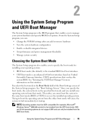
... operating system from the BIOS boot mode. DOS and 32-bit operating systems do not support UEFI and can : • Change the NVRAM settings after you add or remove hardware • View the system hardware configuration • Enable or disable integrated devices • Set performance and power management thresholds • Manage system security Choosing the System Boot Mode The System Setup program also enables you to specify the boot mode for installing your operating system: • BIOS boot mode (the default) is the standard BIOS-level boot interface. • UEFI boot mode...
... operating system from the BIOS boot mode. DOS and 32-bit operating systems do not support UEFI and can : • Change the NVRAM settings after you add or remove hardware • View the system hardware configuration • Enable or disable integrated devices • Set performance and power management thresholds • Manage system security Choosing the System Boot Mode The System Setup program also enables you to specify the boot mode for installing your operating system: • BIOS boot mode (the default) is the standard BIOS-level boot interface. • UEFI boot mode...

Hardware Owner's Manual
Page 61
... UEFI, you can set this option to UEFI disables the Boot Sequence, Hard-Disk Drive Sequence, and USB Flash Drive Emulation Type fields. If the system operating system supports Unified Extensible Firmware Interface, you must manually set to BIOS, this field to UEFI. Auto automatically chooses the appropriate emulation type for the device, except for a USB flash drive. Using the System Setup Program and UEFI Boot Manager 61 Setting this field to do so. If Boot Mode is configured as a removable diskette drive, you can access the UEFI boot manager utility...
... UEFI, you can set this option to UEFI disables the Boot Sequence, Hard-Disk Drive Sequence, and USB Flash Drive Emulation Type fields. If the system operating system supports Unified Extensible Firmware Interface, you must manually set to BIOS, this field to UEFI. Auto automatically chooses the appropriate emulation type for the device, except for a USB flash drive. Using the System Setup Program and UEFI Boot Manager 61 Setting this field to do so. If Boot Mode is configured as a removable diskette drive, you can access the UEFI boot manager utility...
Hardware Owner's Manual
Page 120
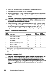
... by Dell is not available. • The expansion-card slots are not hot-swappable. • Besides the integrated storage controller, the system supports a maximum of greater than two of the four expansion cards can have a power consumption of two PERC or SAS controller expansion cards to ensure that the maximum power does not exceed 15W. • When the optional x16-link riser is installed, slot 4 is not covered by your product documentation...
... by Dell is not available. • The expansion-card slots are not hot-swappable. • Besides the integrated storage controller, the system supports a maximum of greater than two of the four expansion cards can have a power consumption of two PERC or SAS controller expansion cards to ensure that the maximum power does not exceed 15W. • When the optional x16-link riser is installed, slot 4 is not covered by your product documentation...

Hardware Owner's Manual
Page 156
... instructions that is not authorized by Dell is not covered by your product documentation, or as directed by a certified service technician. See "Installing System Components." • Cooling shroud • Hard drives • SD cards • USB memory key • NIC hardware key • Internal SD Module • Expansion cards and both expansion-card risers • Integrated storage controller • iDRAC6 Enterprise card 156 Troubleshooting Your System See the documentation for each network device. 7 Ensure that the appropriate drivers are installed...
... instructions that is not authorized by Dell is not covered by your product documentation, or as directed by a certified service technician. See "Installing System Components." • Cooling shroud • Hard drives • SD cards • USB memory key • NIC hardware key • Internal SD Module • Expansion cards and both expansion-card risers • Integrated storage controller • iDRAC6 Enterprise card 156 Troubleshooting Your System See the documentation for each network device. 7 Ensure that the appropriate drivers are installed...

Hardware Owner's Manual
Page 157
.... 1 Turn off the system and attached peripherals, and disconnect the system from the electrical outlet. 2 Open the system. Read and follow the safety instructions that the following components are properly installed: • Expansion cards and both expansion-card risers • Power supplies • Fans and cooling shroud • Processors and heat sinks Troubleshooting Your System 157 If the tests fail, see "Getting Help." 8 If the system starts...
.... 1 Turn off the system and attached peripherals, and disconnect the system from the electrical outlet. 2 Open the system. Read and follow the safety instructions that the following components are properly installed: • Expansion cards and both expansion-card risers • Power supplies • Fans and cooling shroud • Processors and heat sinks Troubleshooting Your System 157 If the tests fail, see "Getting Help." 8 If the system starts...
Hardware Owner's Manual
Page 164
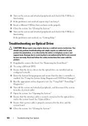
... drive's controller is enabled. See "Using Dell™ PowerEdge™ Diagnostics." 6 Turn off the system and attached peripherals, and disconnect the system from the electrical outlet. 7 Open the system. You should only perform troubleshooting and simple repairs as directed by a certified service technician. See "Removing the Front Bezel." 2 Try using a different DVD. 3 Ensure that the device drivers for the optical drive are installed and are configured correctly 4 Enter the System Setup...
... drive's controller is enabled. See "Using Dell™ PowerEdge™ Diagnostics." 6 Turn off the system and attached peripherals, and disconnect the system from the electrical outlet. 7 Open the system. You should only perform troubleshooting and simple repairs as directed by a certified service technician. See "Removing the Front Bezel." 2 Try using a different DVD. 3 Ensure that the device drivers for the optical drive are installed and are configured correctly 4 Enter the System Setup...

Hardware Owner's Manual
Page 170
... pins can permanently damage the system board. 13 Remove processor 2. Read and follow the safety instructions that each processor and heat sink are properly installed. See "Installing a Processor." 6 Replace the cooling shroud. CAUTION: Be careful not to bend any of the pins on the system and attached peripherals. 9 Run the appropriate online diagnostic test. See "Using Dell™ PowerEdge™ Diagnostics." 2 Turn off the system and attached peripherals...
... pins can permanently damage the system board. 13 Remove processor 2. Read and follow the safety instructions that each processor and heat sink are properly installed. See "Installing a Processor." 6 Replace the cooling shroud. CAUTION: Be careful not to bend any of the pins on the system and attached peripherals. 9 Run the appropriate online diagnostic test. See "Using Dell™ PowerEdge™ Diagnostics." 2 Turn off the system and attached peripherals...
Hardware Owner's Manual
Page 192
... - expansion card - driver - Electrostatic discharge. See iDRAC. A connector on both the rising and falling pulses of automatically assigning an IP address to interface correctly with networked storage devices. 192 Glossary Fibre Channel - A high-speed network interface used by providing an interface between the expansion bus and a peripheral. DIMM - DVD - Error checking and correction. Your system contains an expansion bus that potentially doubles the data rate by transferring data on the system board or riser board for...
... - expansion card - driver - Electrostatic discharge. See iDRAC. A connector on both the rising and falling pulses of automatically assigning an IP address to interface correctly with networked storage devices. 192 Glossary Fibre Channel - A high-speed network interface used by providing an interface between the expansion bus and a peripheral. DIMM - DVD - Error checking and correction. Your system contains an expansion bus that potentially doubles the data rate by transferring data on the system board or riser board for...
Hardware Owner's Manual
Page 206
... panel assembly, 143 SAS backplane, 146 system board, 148 setup password, 72 SSD hard drives, 80 startup accessing system features, 11 storage controller cabling for 2.5-in HDD chassis, 114 cabling for four 3.5-in HDD chassis, 115 cabling for six 3.5-in HDD chassis, 116 installing, 112 removing, 112 troubleshooting, 167 support contacting Dell, 189 system board connectors, 180 installing, 150 jumpers, 177 removing, 148 system cooling troubleshooting, 159 system features accessing, 11 system messages, 37 system password, 70 system setup program boot settings, 61 embedded server management...
... panel assembly, 143 SAS backplane, 146 system board, 148 setup password, 72 SSD hard drives, 80 startup accessing system features, 11 storage controller cabling for 2.5-in HDD chassis, 114 cabling for four 3.5-in HDD chassis, 115 cabling for six 3.5-in HDD chassis, 116 installing, 112 removing, 112 troubleshooting, 167 support contacting Dell, 189 system board connectors, 180 installing, 150 jumpers, 177 removing, 148 system cooling troubleshooting, 159 system features accessing, 11 system messages, 37 system password, 70 system setup program boot settings, 61 embedded server management...


