
Hardware Owner's Manual
Page 76
... for optional internal USB key 3 hot-swappable cooling fans (4 or 5) 5 processors (1 or 2) 7 riser 2 (PCIe slots 3 and 4) 9 iDRAC6 Enterprise card (optional) 11 SAS backplane 13 RAID battery (PERC only) 15 control panel 2 Internal SD Module 4 memory modules (up to 18 total, 9 for each processor) 6 power supply bays (2) 8 riser 1 (PCIe slots 1 and 2) 10 integrated...
... for optional internal USB key 3 hot-swappable cooling fans (4 or 5) 5 processors (1 or 2) 7 riser 2 (PCIe slots 3 and 4) 9 iDRAC6 Enterprise card (optional) 11 SAS backplane 13 RAID battery (PERC only) 15 control panel 2 Internal SD Module 4 memory modules (up to 18 total, 9 for each processor) 6 power supply bays (2) 8 riser 1 (PCIe slots 1 and 2) 10 integrated...
Hardware Owner's Manual
Page 112
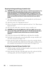
...controller memory and the data was not cleared at system shutdown. 5 If necessary, disconnect the RAID battery cable from the electrical outlet. 2 Open the system. CAUTION: Disconnecting the RAID battery cable from a PERC card can cause data loss if the "dirty cache" LED on the blue card-edge guide, ...release the controller, lift the side of the chassis. Removing the Integrated Storage Controller Card CAUTION: Many repairs may only be done by Dell is still cached in your warranty. Read and follow the safety instructions that data is not covered by your product documentation, or as ...
...controller memory and the data was not cleared at system shutdown. 5 If necessary, disconnect the RAID battery cable from the electrical outlet. 2 Open the system. CAUTION: Disconnecting the RAID battery cable from a PERC card can cause data loss if the "dirty cache" LED on the blue card-edge guide, ...release the controller, lift the side of the chassis. Removing the Integrated Storage Controller Card CAUTION: Many repairs may only be done by Dell is still cached in your warranty. Read and follow the safety instructions that data is not covered by your product documentation, or as ...

Hardware Owner's Manual
Page 113
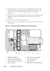
... 5 8 7 6 1 dedicated storage controller card connector 3 integrated storage controller card 5 SAS_1 connector 7 SAS_0 connector 2 riser 1 4 RAID battery connector (PERC only) 6 connector locking tabs 8 card edge guides (2) 3 Slide the storage controller's card edge connector into the card slot on the cable.... Installing System Components 113 The cables are not operational if reversed. 5 For a battery-cached PERC controller, install the RAID battery. See "Installing a RAID Battery." See Figure 3-20. 4 Connect the SAS_0 cable to the storage controller's SAS_0 connector, and...
... 5 8 7 6 1 dedicated storage controller card connector 3 integrated storage controller card 5 SAS_1 connector 7 SAS_0 connector 2 riser 1 4 RAID battery connector (PERC only) 6 connector locking tabs 8 card edge guides (2) 3 Slide the storage controller's card edge connector into the card slot on the cable.... Installing System Components 113 The cables are not operational if reversed. 5 For a battery-cached PERC controller, install the RAID battery. See "Installing a RAID Battery." See Figure 3-20. 4 Connect the SAS_0 cable to the storage controller's SAS_0 connector, and...
Hardware Owner's Manual
Page 114
...their electrical outlets, and turn on the system. 6 If not already done, route the interface and RAID battery cables in Hard-Drive Chassis) 1 2 3 45 6 78 1 RAID battery (PERC only) 3 SAS A connector on backplane 5 integrated storage controller card 7 SAS_1 connector 2 SAS B ...connector on backplane 4 cable retention bracket 6 SAS_0 connector 8 RAID battery connector (PERC only) 114 Installing System Components See "Closing the System...
...their electrical outlets, and turn on the system. 6 If not already done, route the interface and RAID battery cables in Hard-Drive Chassis) 1 2 3 45 6 78 1 RAID battery (PERC only) 3 SAS A connector on backplane 5 integrated storage controller card 7 SAS_1 connector 2 SAS B ...connector on backplane 4 cable retention bracket 6 SAS_0 connector 8 RAID battery connector (PERC only) 114 Installing System Components See "Closing the System...

Hardware Owner's Manual
Page 115
Figure 3-22. Storage Controller Card Cabling (Six 3.5-in Hard-Drive Chassis) 1 2 3 45 6 78 1 RAID battery (PERC only) 3 SAS A connector on backplane 5 integrated storage controller card 7 SAS_1 connector 2 SAS B connector on backplane 4 cable retention bracket 6 SAS_0 connector 8 RAID battery connector (PERC only) Installing System Components 115
Figure 3-22. Storage Controller Card Cabling (Six 3.5-in Hard-Drive Chassis) 1 2 3 45 6 78 1 RAID battery (PERC only) 3 SAS A connector on backplane 5 integrated storage controller card 7 SAS_1 connector 2 SAS B connector on backplane 4 cable retention bracket 6 SAS_0 connector 8 RAID battery connector (PERC only) Installing System Components 115

Hardware Owner's Manual
Page 116
Storage Controller Card Cabling (Four 3.5-inch Hard Drive Chassis) 1 2 34 5 6 1 RAID battery (PERC only) 3 cable retention bracket 5 SAS_0 connector 2 SAS A connector on the right edge of the battery bay and draw out the RAID battery from the battery carrier. 2 Disconnect the cable between the RAID battery and the storage controller card. See Figure 3-24. 116 Installing System...
Storage Controller Card Cabling (Four 3.5-inch Hard Drive Chassis) 1 2 34 5 6 1 RAID battery (PERC only) 3 cable retention bracket 5 SAS_0 connector 2 SAS A connector on the right edge of the battery bay and draw out the RAID battery from the battery carrier. 2 Disconnect the cable between the RAID battery and the storage controller card. See Figure 3-24. 116 Installing System...

Hardware Owner's Manual
Page 168
... the system and attached peripherals, and disconnect the system from its electrical outlet, and turn on the PERC card is properly seated. 9 Verify that the RAID battery is not covered by a certified service technician. NOTE: When troubleshooting an expansion card, see "Getting ...Controller Card." 8 If you have a battery-cached PERC controller, ensure that the cable connections between the SAS backplane and the integrated storage controller are firmly connected to its electrical outlet. 6 Open the system. See "Using Dell™ PowerEdge™ Diagnostics." 2 Turn off the system...
... the system and attached peripherals, and disconnect the system from its electrical outlet, and turn on the PERC card is properly seated. 9 Verify that the RAID battery is not covered by a certified service technician. NOTE: When troubleshooting an expansion card, see "Getting ...Controller Card." 8 If you have a battery-cached PERC controller, ensure that the cable connections between the SAS backplane and the integrated storage controller are firmly connected to its electrical outlet. 6 Open the system. See "Using Dell™ PowerEdge™ Diagnostics." 2 Turn off the system...


