
Glossary
Page 1
...standard interface for developing technology standards in the U.S. ambient temperature - A module that includes power supplies and fans. BTU - Certificate authority. Common Information Model describes the management information utilized by an administrator, for interchange... and Power Interface. American National Standards Institute. blade - BMC - bootable media - British thermal unit. Celsius. CIM - cm - Dell™ Glossary NOTE: For additional information on storage terminology, visit the Storage Networking Industry Association's website at www.snia.org and click on...
...standard interface for developing technology standards in the U.S. ambient temperature - A module that includes power supplies and fans. BTU - Certificate authority. Common Information Model describes the management information utilized by an administrator, for interchange... and Power Interface. American National Standards Institute. blade - BMC - bootable media - British thermal unit. Celsius. CIM - cm - Dell™ Glossary NOTE: For additional information on storage terminology, visit the Storage Networking Industry Association's website at www.snia.org and click on...

Glossary
Page 3
... referring to 1,000,000,000 bytes. The ability to insert or install a device, typically a hard drive or an internal cooling fan, into the host system while the system is usually rounded to hard-drive capacity, the term is powered on the system board or... riser board for connection of processors with networked storage devices. I /O activity can optionally use a FAT file system structure. iDRAC - Integrated Dell Remote Access Controller. InfiniBand offers point-to organize and keep track of electronic chip that uses the Internet SCSI protocol. IP - Internet Protocol version...
... referring to 1,000,000,000 bytes. The ability to insert or install a device, typically a hard drive or an internal cooling fan, into the host system while the system is usually rounded to hard-drive capacity, the term is powered on the system board or... riser board for connection of processors with networked storage devices. I /O activity can optionally use a FAT file system structure. iDRAC - Integrated Dell Remote Access Controller. InfiniBand offers point-to organize and keep track of electronic chip that uses the Internet SCSI protocol. IP - Internet Protocol version...

Hardware Owner's Manual
Page 6
...91 Internal USB Memory Key 91 Internal USB Cable 93 Removing the Internal USB Cable 93 Installing the Internal USB Cable 93 Integrated Dell Remote Access Controller 6 (iDRAC6) Enterprise Card (Optional 94 Installing an iDRAC6 Enterprise Card 94 Removing an iDRAC6 Enterprise Card 95...97 Cooling Shroud 98 Removing the Cooling Shroud 99 Installing the Cooling Shroud 100 Cooling Fans 100 Removing a Cooling Fan 100 Replacing a Cooling Fan 101 Removing the Fan Bracket 102 Replacing the Fan Bracket 103 Optical Drive 103 Removing the Optical Drive 104 Installing the Optical Drive 104 ...
...91 Internal USB Memory Key 91 Internal USB Cable 93 Removing the Internal USB Cable 93 Installing the Internal USB Cable 93 Integrated Dell Remote Access Controller 6 (iDRAC6) Enterprise Card (Optional 94 Installing an iDRAC6 Enterprise Card 94 Removing an iDRAC6 Enterprise Card 95...97 Cooling Shroud 98 Removing the Cooling Shroud 99 Installing the Cooling Shroud 100 Cooling Fans 100 Removing a Cooling Fan 100 Replacing a Cooling Fan 101 Removing the Fan Bracket 102 Replacing the Fan Bracket 103 Optical Drive 103 Removing the Optical Drive 104 Installing the Optical Drive 104 ...

Hardware Owner's Manual
Page 9
... 156 Troubleshooting a Damaged System 157 Troubleshooting the System Battery 158 Troubleshooting Power Supplies 158 Troubleshooting System Cooling Problems 159 Troubleshooting a Fan 160 Troubleshooting System Memory 160 Troubleshooting an Internal SD Card 162 Troubleshooting an Internal USB Memory Key . . . . . 163... Cards 168 Troubleshooting the Processor(s 170 5 Running the System Diagnostics . . . . . 173 Using Dell™ PowerEdge™ Diagnostics 173 System Diagnostics Features 173 When to Use the System Diagnostics 174 Running the System Diagnostics 174 Contents 9
... 156 Troubleshooting a Damaged System 157 Troubleshooting the System Battery 158 Troubleshooting Power Supplies 158 Troubleshooting System Cooling Problems 159 Troubleshooting a Fan 160 Troubleshooting System Memory 160 Troubleshooting an Internal SD Card 162 Troubleshooting an Internal USB Memory Key . . . . . 163... Cards 168 Troubleshooting the Processor(s 170 5 Running the System Diagnostics . . . . . 173 Using Dell™ PowerEdge™ Diagnostics 173 System Diagnostics Features 173 When to Use the System Diagnostics 174 Running the System Diagnostics 174 Contents 9
Hardware Owner's Manual
Page 23
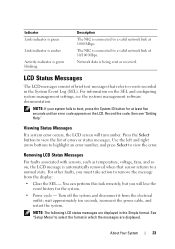
... the system. Record the code, then see the systems management software documentation. Removing LCD Status Messages For faults associated with sensors, such as temperature, voltage, fans, and so on the LCD. See "Setup Menu" to select the format in which the messages are displayed in the System Event Log (SEL). About...
... the system. Record the code, then see the systems management software documentation. Removing LCD Status Messages For faults associated with sensors, such as temperature, voltage, fans, and so on the LCD. See "Setup Menu" to select the format in which the messages are displayed in the System Event Log (SEL). About...

Hardware Owner's Manual
Page 25
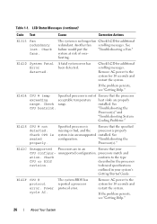
...regulator has failed. Specified processor VTT Reseat the processor(s). See "Troubleshooting the Processor(s)." Power cycle AC. Check fan. See "Troubleshooting the Processor(s)." voltage regulator has failed. If the problem persists, see "Getting Help." restart ...Regulator failure. One of the memory Regulator # regulators has failed. Check fan. If the problem persists, see "Getting Help." See "Troubleshooting System Cooling Problems." Reseat the processor(s). E1311 Fan module ## RPM exceeding range. Table 1-1. LCD Status Messages (continued) ...
...regulator has failed. Specified processor VTT Reseat the processor(s). See "Troubleshooting the Processor(s)." Power cycle AC. Check fan. See "Troubleshooting the Processor(s)." voltage regulator has failed. If the problem persists, see "Getting Help." restart ...Regulator failure. One of the memory Regulator # regulators has failed. Check fan. If the problem persists, see "Getting Help." See "Troubleshooting System Cooling Problems." Reseat the processor(s). E1311 Fan module ## RPM exceeding range. Table 1-1. LCD Status Messages (continued) ...
Hardware Owner's Manual
Page 26
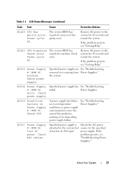
... range. Remove AC power to the system for additional redundant. E1414 CPU # temp Specified processor is no longer fan Check LCD for 10 seconds and restart the system. Check range. "Troubleshooting the Processor(s)." If the problem persists, see "Getting Help."...processor exceeding acceptable temperature heat sinks are in your CPU configur- The system BIOS has reported a processor protocol error. Check fans. Check conform to the system for additional scrolling messages. Power cycle AC. Table 1-1. LCD Status Messages (continued) Code Text Cause ...
... range. Remove AC power to the system for additional redundant. E1414 CPU # temp Specified processor is no longer fan Check LCD for 10 seconds and restart the system. Check range. "Troubleshooting the Processor(s)." If the problem persists, see "Getting Help."...processor exceeding acceptable temperature heat sinks are in your CPU configur- The system BIOS has reported a processor protocol error. Check fans. Check conform to the system for additional scrolling messages. Power cycle AC. Table 1-1. LCD Status Messages (continued) Code Text Cause ...
Hardware Owner's Manual
Page 27
... (continued) Code Text Cause Corrective Actions E1420 CPU Bus The system BIOS has parity error. The system BIOS has reported a machine check error. A power supply fan failure, an over-temperature condition, or power supply communication error has caused the predictive warning of an impending power supply failure. About Your System 27...
... (continued) Code Text Cause Corrective Actions E1420 CPU Bus The system BIOS has parity error. The system BIOS has reported a machine check error. A power supply fan failure, an over-temperature condition, or power supply communication error has caused the predictive warning of an impending power supply failure. About Your System 27...

Hardware Owner's Manual
Page 53
... you to a possible problem and prompts you to respond by either the application or the operating system. See "Running the System Diagnostics" for drive, temperature, fan, and power conditions. NOTE: For the full name of an abbreviation or acronym used in this table, see the documentation that the USB, assembly, hard...
... you to a possible problem and prompts you to respond by either the application or the operating system. See "Running the System Diagnostics" for drive, temperature, fan, and power conditions. NOTE: For the full name of an abbreviation or acronym used in this table, see the documentation that the USB, assembly, hard...
Hardware Owner's Manual
Page 58
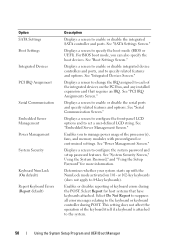
... the serial ports and specify related features and options. See "Integrated Devices Screen." Displays a screen to change the IRQ assigned to each of the processor(s), fans, and memory modules with the NumLock mode activated on the PCI bus, and any installed expansion card that have keyboards attached. Enables you can also...
... the serial ports and specify related features and options. See "Integrated Devices Screen." Displays a screen to change the IRQ assigned to each of the processor(s), fans, and memory modules with the NumLock mode activated on the PCI bus, and any installed expansion card that have keyboards attached. Enables you can also...

Hardware Owner's Manual
Page 65
Power Management Screen Option Power Management CPU Power and Performance Management Fan Power and Performance Management Memory Power and Performance Management Description Options are Maximum Performance or Minimum Power. The BIOS sets the processor performance based on ... is passed from the system BIOS to Maximum Performance. In this screen as follows: • OS Control sets the CPU power to OS DBPM, the fan power to Minimum Power, and the memory power to Maximum Performance. If you select Custom, you can configure each option independently. Options are Maximum Performance...
Power Management Screen Option Power Management CPU Power and Performance Management Fan Power and Performance Management Memory Power and Performance Management Description Options are Maximum Performance or Minimum Power. The BIOS sets the processor performance based on ... is passed from the system BIOS to Maximum Performance. In this screen as follows: • OS Control sets the CPU power to OS DBPM, the fan power to Minimum Power, and the memory power to Maximum Performance. If you select Custom, you can configure each option independently. Options are Maximum Performance...

Hardware Owner's Manual
Page 76
Figure 3-1. Inside the System (2.5-Inch Hard-Drive Chassis) 6 5 4 3 2 1 7 8 9 16 15 14 13 12 10 11 1 USB connector for optional internal USB key 3 hot-swappable cooling fans (4 or 5) 5 processors (1 or 2) 7 riser 2 (PCIe slots 3 and 4) 9 iDRAC6 Enterprise card (optional) 11 SAS backplane 13 RAID battery (PERC only) 15 control panel 2 Internal SD Module 4 ...
Figure 3-1. Inside the System (2.5-Inch Hard-Drive Chassis) 6 5 4 3 2 1 7 8 9 16 15 14 13 12 10 11 1 USB connector for optional internal USB key 3 hot-swappable cooling fans (4 or 5) 5 processors (1 or 2) 7 riser 2 (PCIe slots 3 and 4) 9 iDRAC6 Enterprise card (optional) 11 SAS backplane 13 RAID battery (PERC only) 15 control panel 2 Internal SD Module 4 ...

Hardware Owner's Manual
Page 79
...lift the system, get others to assist you are installing a hot-swappable component such as directed by your product documentation, or as a cooling fan or power supply, turn off the system and attached peripherals, and disconnect the system from the system. Closing the System 1 Lift up on ...with the product. You should only perform troubleshooting and simple repairs as authorized in a clockwise direction to servicing that is not authorized by Dell is not covered by the online or telephone service and support team. Read and follow the safety instructions that it clears the chassis hooks...
...lift the system, get others to assist you are installing a hot-swappable component such as directed by your product documentation, or as a cooling fan or power supply, turn off the system and attached peripherals, and disconnect the system from the system. Closing the System 1 Lift up on ...with the product. You should only perform troubleshooting and simple repairs as authorized in a clockwise direction to servicing that is not authorized by Dell is not covered by the online or telephone service and support team. Read and follow the safety instructions that it clears the chassis hooks...

Hardware Owner's Manual
Page 93
...in your product documentation, or as directed by the online or telephone service and support team. See "Opening the System." 3 Remove the fan bracket. If necessary remove any attached peripherals, and disconnect the system from the electrical outlet. 2 Open the system. Read and follow the... Damage due to the connector on the system board. 7 Replace the fan bracket. See "Replacing the Fan Bracket." See "Removing the Fan Bracket." 4 Connect the USB cable to servicing that is not authorized by Dell is not covered by your warranty. Internal USB Cable Removing the Internal USB...
...in your product documentation, or as directed by the online or telephone service and support team. See "Opening the System." 3 Remove the fan bracket. If necessary remove any attached peripherals, and disconnect the system from the electrical outlet. 2 Open the system. Read and follow the... Damage due to the connector on the system board. 7 Replace the fan bracket. See "Replacing the Fan Bracket." See "Removing the Fan Bracket." 4 Connect the USB cable to servicing that is not authorized by Dell is not covered by your warranty. Internal USB Cable Removing the Internal USB...
Hardware Owner's Manual
Page 98
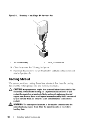
...only perform troubleshooting and simple repairs as authorized in your warranty. Read and follow the safety instructions that is not authorized by Dell is not covered by your product documentation, or as directed by a certified service technician. Damage due to the electrical outlet ...Reconnect the system to servicing that came with the product. Cooling Shroud The system provides a cooling shroud that directs airflow from the cooling fans over the system processor(s) and memory module(s). Figure 3-11. Removing or Installing a NIC Hardware Key 1 2 1 NIC hardware key 2 ISCSI_KEY connector ...
...only perform troubleshooting and simple repairs as authorized in your warranty. Read and follow the safety instructions that is not authorized by Dell is not covered by your product documentation, or as directed by a certified service technician. Damage due to the electrical outlet ...Reconnect the system to servicing that came with the product. Cooling Shroud The system provides a cooling shroud that directs airflow from the cooling fans over the system processor(s) and memory module(s). Figure 3-11. Removing or Installing a NIC Hardware Key 1 2 1 NIC hardware key 2 ISCSI_KEY connector ...
Hardware Owner's Manual
Page 100
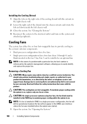
...in your warranty. NOTE: If a fan is not covered by Dell is installed in FAN5 in a single-processor configuration, the fan will not appear in the iDRAC user interface unless the fan was installed before the system was started. 1 Open the system. Cooling Fans The system has either five or four... hot-swappable fans to provide cooling...
...in your warranty. NOTE: If a fan is not covered by Dell is installed in FAN5 in a single-processor configuration, the fan will not appear in the iDRAC user interface unless the fan was installed before the system was started. 1 Open the system. Cooling Fans The system has either five or four... hot-swappable fans to provide cooling...

Hardware Owner's Manual
Page 101
Removing and Installing a Cooling Fan 2 1 3 1 fan 3 fan bracket 2 fan release handle Replacing a Cooling Fan 1 Align the fan plug with the connector at the base of the fan and lift the fan straight up from the fan bracket. Installing System Components 101 WARNING: Use caution when handling the fan until the fan blades stop spinning. 2 Press the release tab while grasping the ends of the fan bracket and lower the fan into the bracket until the fan is fully seated. Figure 3-13. See "Closing the System." See Figure 3-13. See Figure 3-13. 2 Close the system.
Removing and Installing a Cooling Fan 2 1 3 1 fan 3 fan bracket 2 fan release handle Replacing a Cooling Fan 1 Align the fan plug with the connector at the base of the fan and lift the fan straight up from the fan bracket. Installing System Components 101 WARNING: Use caution when handling the fan until the fan blades stop spinning. 2 Press the release tab while grasping the ends of the fan bracket and lower the fan into the bracket until the fan is fully seated. Figure 3-13. See "Closing the System." See Figure 3-13. See Figure 3-13. 2 Close the system.

Hardware Owner's Manual
Page 102
... CAUTION: Many repairs may only be done by your product documentation, or as authorized in your warranty. See "Opening the System." 3 Optional: Remove the fans from the electrical outlet. 2 Open the system. You should only perform troubleshooting and simple repairs as directed by the online or telephone service and support ...team. See Figure 3-14. 102 Installing System Components Read and follow the safety instructions that is not authorized by Dell is not covered by a certified service technician.
... CAUTION: Many repairs may only be done by your product documentation, or as authorized in your warranty. See "Opening the System." 3 Optional: Remove the fans from the electrical outlet. 2 Open the system. You should only perform troubleshooting and simple repairs as directed by the online or telephone service and support ...team. See Figure 3-14. 102 Installing System Components Read and follow the safety instructions that is not authorized by Dell is not covered by a certified service technician.

Hardware Owner's Manual
Page 103
See "Replacing a Cooling Fan." 4 Close the system. Figure 3-14. See "Closing the System." Installing System Components 103 Optical Drive An optional slimline DVD-ROM or DVD+RW optical drive .... The optical drive is on the right or left side of the system, depending on system board 2 release latch 4 mounting pin Replacing the Fan Bracket 1 Align the fan bracket down onto the bracket base so that the mounting pins fit correctly into the front panel and connects to lock it in place...
See "Replacing a Cooling Fan." 4 Close the system. Figure 3-14. See "Closing the System." Installing System Components 103 Optical Drive An optional slimline DVD-ROM or DVD+RW optical drive .... The optical drive is on the right or left side of the system, depending on system board 2 release latch 4 mounting pin Replacing the Fan Bracket 1 Align the fan bracket down onto the bracket base so that the mounting pins fit correctly into the front panel and connects to lock it in place...

Hardware Owner's Manual
Page 105
... the system. See "Cable Routing" and Figure 3-16 for the 2.5-inch backplane chassis or Figure 3-17 for the location of the system board below the fan bracket. See "Closing the System." 9 Replace the bezel. Removing and Installing the Optical Drive 2 3 1 4 1 optical drive 3 power cable 2 optical-drive interface cable 4 optical-drive release...
... the system. See "Cable Routing" and Figure 3-16 for the 2.5-inch backplane chassis or Figure 3-17 for the location of the system board below the fan bracket. See "Closing the System." 9 Replace the bezel. Removing and Installing the Optical Drive 2 3 1 4 1 optical drive 3 power cable 2 optical-drive interface cable 4 optical-drive release...


